Intelligent domestic network system bus interface unit

A bus interface unit and network system technology, applied in the field of home bus interface unit design, can solve problems such as unclear communication levels, many technical terms, and difficult configuration systems, so as to reduce engineering wiring costs, operate correctly and reliably, and improve flexibility Effect

Inactive Publication Date: 2002-11-20
TSINGHUA UNIV +1
View PDF1 Cites 11 Cited by
  • Summary
  • Abstract
  • Description
  • Claims
  • Application Information

AI Technical Summary

Problems solved by technology

[0014] First, the system composed of the bus interface unit has complex system configuration: the system does not use a graphical interface, and there are many technical terms in the configuration, which does not well shield the relationship between the user and the application hardware
As a result, the system has relatively high basic technical requirements for configuration personnel. For users who do not have electrical and control knowledge or are not familiar with the system, it is difficult to configure the system and does not meet the flexible and convenient requirements of the system.
It shows that the internal communication mechanism of the bus interface unit is not flexible
[0015] Second, the structure of this system is not perfect, and the communication level is not clear
[0017] Fourth, although there is an infrared remote control device in the system, the remote control of home appliances only relies on the simple imitation of the signals sent by the infrared module in the system to the remote control of home appliances, and does not really connect home appliances to the home bus, and data communication is only One-way, only one-way control of home appliances, unable to collect device status in the home system
It shows that the function of the bus interface unit design is not perfect

Method used


Image

  • Intelligent domestic network system bus interface unit
  • Intelligent domestic network system bus interface unit
  • Intelligent domestic network system bus interface unit

Examples


Embodiment Construction

[0049] The smart home network system bus interface unit of the present invention is described in detail as follows for its composition and functions in conjunction with the accompanying drawings and embodiments:

[0050] The bus interface unit of the present invention is described as follows respectively:

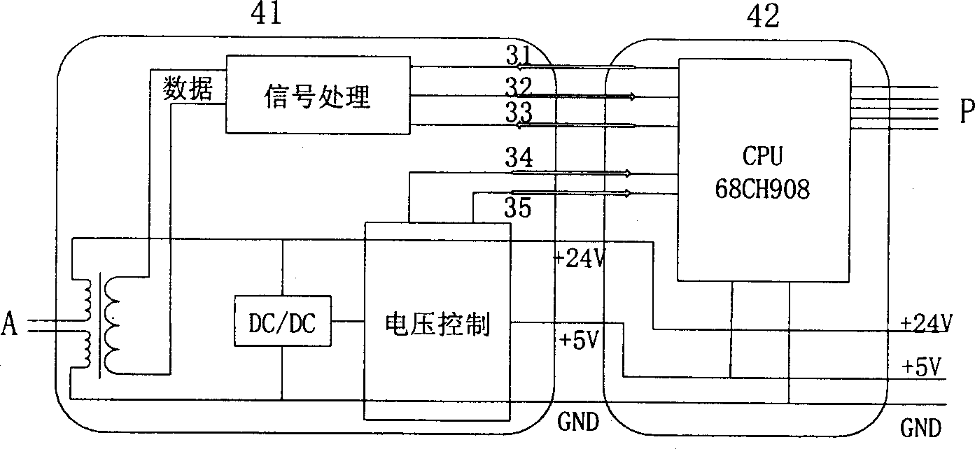
[0051] The hardware of the bus interface unit of the present invention is as image 3 As shown, it consists of two modules, a data transceiver module 41 and a communication controller 42 connected to it. Wherein, the signal processing module in the data transceiver module 41 is connected to the CPU in the communication controller 42 through three communication lines 31 sending, 32 receiving, and 33 controlling. The voltage control module in the data transceiver module 41 is connected to the CPU in the communication controller 42 through 34 saving, 35 resetting, and two control lines. The general-purpose external interface in the communication controller 42 is connected wi...


PUM


Abstract

The invented bus type interface unit used in an intelligent home network system belongs to the area of the intelligent home system in bus network type. The sand unit incldues the module for receivingand transmitting data, the communication controller connected to the said module as well as the software module stored on the unit and being composed of the system programs and application programs. The module for receiving and transmitting data consists of the transformer, DC/DC converter connected to the said transformer, the voltage control circuit and the signal processing circuit. The signalprocessing circuit is connected to the communication controller through three communications wires, transmission, receive and control. The voltage control module is connected to the communication controller through two controlling wires: save and reset.

Description

technical field [0001] The invention belongs to the technical field of smart home systems in the form of a bus network, and particularly relates to a home bus interface for connecting home devices with the bus inside the smart home, assisting the home devices in completing data communication on the bus, and performing corresponding operations on the home devices unit design. Background technique [0002] The smart home network system refers to connecting various electrical equipment and electrical subsystems to form a home network through a certain transmission medium (such as power lines, twisted pairs, radios, etc.) Sharing; it can be interconnected with external networks (such as Internet, ISDN, HFC, etc.) through the gateway for information exchange. The following functions can be realized through the home network: [0003] 1. Control and management of electrical equipment [0004] Lights, water heaters, air conditioners and other electrical equipment can be controlle...

Claims


Application Information

Patent Timeline
Patent Type & Authority Applications(China)
IPC IPC(8): G06F13/10G06F13/42
Inventor 杨士元叶朝辉徐海谢宇俊潘龙董炜热娜古丽
Owner TSINGHUA UNIV
Why Eureka
Try Eureka