
Stack structure

A structure and chimney technology, which can be applied in the treatment of combustion products, combustion methods, and chemical separation, etc., and can solve problems such as global warming

Inactive Publication Date: 2003-01-15
MARUKI
View PDF0 Cites 12 Cited by
  • Summary
  • Abstract
  • Description
  • Claims
  • Application Information

AI Technical Summary

Problems solved by technology

But in recent years, the carbon dioxide in the atmosphere has increased dramatically, causing the serious problem of global warming

Method used


Image

  • Stack structure
  • Stack structure
  • Stack structure

Examples


no. 2 Embodiment

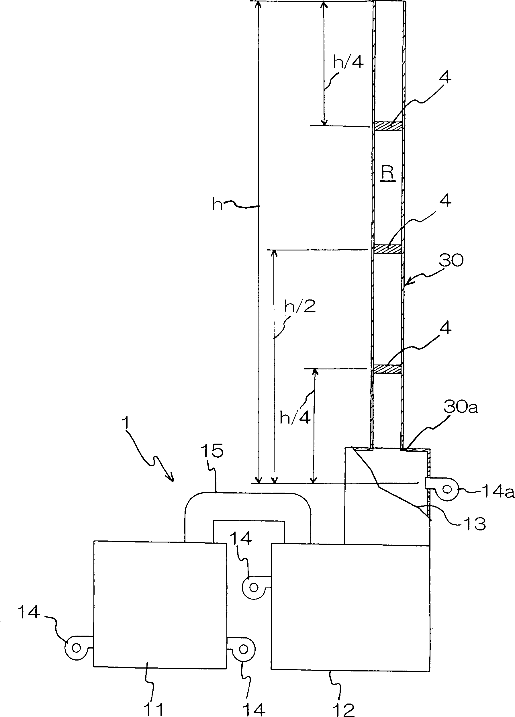
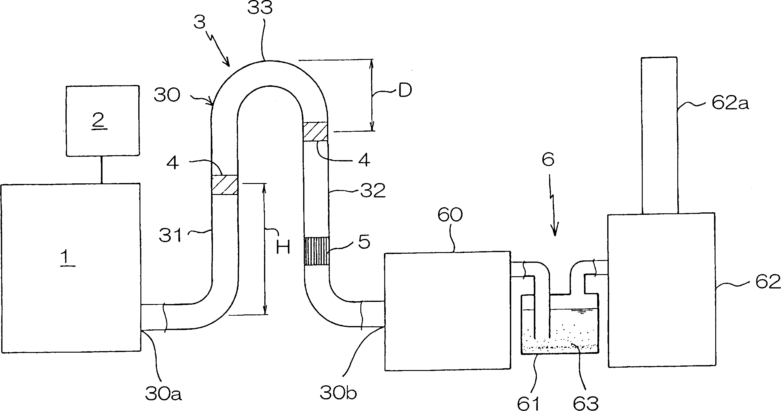
[0080] figure 2 It is a schematic explanatory drawing showing the chimney structure of the second embodiment. Among the figure, 1 is the combustion chamber of the refuse incinerator, and desulfurization device 2 is attached. The combustion chamber 1 in this embodiment can perform high-temperature combustion at 1250 to 1450°C in order to suppress generation of dioxin and the like. In addition, a secondary combustion chamber (not shown) may also be provided. In the combustion chamber 1, combustion at about 800° C. is carried out, and high-temperature combustion is carried out in the secondary combustion chamber to form incineration ash and fly ash into molten slag.

[0081] In the above structure, the feature of this embodiment is that the pipe body 30 of the chimney 3 extends upwards, bends downward in the middle, and is formed into an inverted U shape. The above-mentioned porous laminates 4 are arranged in the middle of the vertical portion 32 .

[0082] In addition, an ex...


PUM


Abstract

The invention aims to provide a chimney structure capable of preventing carbon dioxide causing global warming from being exhausted into the atmosphere, wherein: a porous stack is disposed in a pipe body having a base end communicating with a combustion chamber. In addition, the pipe body is formed by bending it in an inverted U-shape, and a porous stack is disposed in the combustion gas flow path.

Description

technical field [0001] The present invention relates to a chimney structure capable of reducing the height of the chimney by half and removing harmful carbon dioxide in combustion gas. Background technique [0002] In the past, chimneys with a height of tens of meters were often installed in waste incineration plants and the like. [0003] In order to prevent harmful substances such as dust flying from the chimney from affecting nearby areas, it is usually diffused in the sky, but this requires a large construction cost. [0004] In recent years, environmental pollution from exhaust gas such as chimneys has become a global problem, and various studies have been conducted by related departments. [0005] Among them, much research has been done on how to prevent the generation of dioxins from garbage incineration, etc., and an incinerator that can significantly reduce the generation of dioxins has been developed. [0006] But the current situation is that for the carbon diox...

Claims


Application Information

Patent Timeline
Patent Type & Authority Applications(China)
IPC IPC(8): B01D53/62B01D53/86F23G7/06F23G7/08F23J13/02
CPCF23G7/085B01D53/62F23G7/065Y02C10/04B01D53/864F23J13/025Y02C20/40Y02E20/32
Inventor 北野善一
Owner MARUKI
Learn More