High efficiency wet desulfuration and dust-removing device

A technology of wet desulfurization and dust removal device, which is applied to the separation of dispersed particles, chemical instruments and methods, and the use of liquid separators, etc., can solve the problems of short contact time, large drop of fluid resistance in the tower, and low contact probability, and achieve contact reaction. The effect of complete, sufficient desulfurization and dust removal, and sufficient gas-liquid mixing

Inactive Publication Date: 2003-01-22
ZHEJIANG BOHUA ENVIRONMENTAL TECH & ENG
View PDF2 Cites 13 Cited by
  • Summary
  • Abstract
  • Description
  • Claims
  • Application Information

AI Technical Summary

Problems solved by technology

This swirl plate tower also has the following disadvantages: 1) its flue gas inlet is arranged at the bottom of the tower, the flue gas outlet is arranged at the top of the tower, the liquid flow inlet is arranged at the top of the tower, and the liquid flow outlet is arranged at the bottom of the tower, so , its desulfurization and dust removal is completed in the reverse flow contact between the downward liquid flow and the upward air flow. Because the liquid and gas in the reverse flow have a short contact time and a small contact probability, the effect of desulfurization and dust removal is not ideal; 2) Swirling flow The structure of the plate tower is complicated, there are many parts, and the requirements for installation are relatively strict, such as whether the swirl tray is horizontal or not, whether the installation of the guide vane is centered, whether the center liquid receiving plate and the short cylindrical shell are in the circumferential direction. Whether the distance between each point is uniform or not will directly affect the effect of desulfurization and dust removal, so it is relatively difficult and costly in terms of equipment manufacturing and installation; 3) Complete flue gas desulfurization in gas-liquid reverse flow It takes a lot of liquid medicine to remove dust, and the resistance drop when the fluid passes through the swirl tray is also relatively large, so the cost of equipment operation is relatively high; 4) the swirl tray is easily damaged, and its maintenance is time-consuming and expensive. Troublesome and has to be shut down for repairs
It improves the effect of flue gas desulfurization and dust removal by the flow of liquid and gas in the same direction, simplifies the structure of the equipment, reduces the consumption of liquid medicine and the resistance drop of fluid flow, but it also has the following disadvantages: 1) The The double-tower structure of the main tower and Venturi tower used in the device needs to occupy a large space, and the resistance drop of the fluid in the tower is also relatively large; 2) Its main tower is a straight circular cylindrical shape, and the smoke and liquid medicine After entering from the tangential opening of the tower wall, desulfurization and dust removal are carried out in the swirl layer. Because the fluid lacks radial cross mixing in the swirl layer, the desulfurization reaction is not thorough enough; 3) There is no liquid supplement in the central area of ​​the main tower , there is a significant lack of liquid medicine, and the mist concentrates in the center of the main tower when the fluid rotates. It rises with the air flow and is difficult to remove, so it will affect the further improvement of the desulfurization and dust removal effect and the dryness of the exhaust gas.

Method used


Image

  • High efficiency wet desulfuration and dust-removing device
  • High efficiency wet desulfuration and dust-removing device
  • High efficiency wet desulfuration and dust-removing device

Examples


Embodiment 1

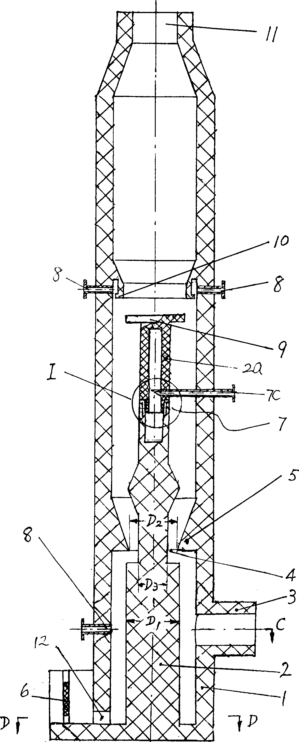
[0017] Embodiment 1. The high-efficiency wet desulfurization and dust removal device of this embodiment can be obtained from figure 1 and figure 2 As can be seen in the figure, it includes an upright main tower 1 with an inner tower 2 in its center, a flue gas outlet pipe 11 is arranged at the top of the main tower, and a tangential flue gas inlet pipe 3 and gray water and desulfurization pipes are arranged at the bottom. The outlet pipe 12 of the slag, the upper and lower parts of the tower wall are respectively provided with a group of tangential liquid spray pipes 8, and the inner wall of the main tower 1 above the top of the inner tower 2 has a water retaining ring 10, and the main tower is located at the flue gas inlet. The inner wall of the tower above the tube 3 is provided with a circle of inner convex ring 5 which can make the channel of the fluid fold to the center of the tower first and then expand gradually upwards.

[0018] The above-mentioned inner convex ring ...

Embodiment 2

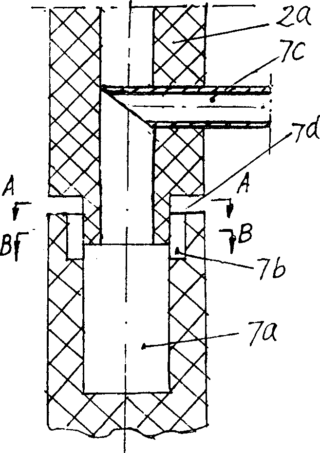
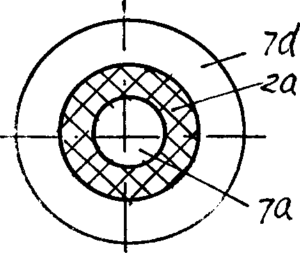
[0020] Embodiment 2. This embodiment can be obtained from figure 1 and figure 2 Seen in, it differs from embodiment 1 in that: the overflow device 7 with liquid medicine in the center of the main tower, this overflow device can be obtained from figure 2 , image 3 and Figure 4As can be seen in the figure, it includes a liquid medicine inlet pipe 7c connected to the wall of the main tower, a liquid medicine pool 7a connected to the liquid medicine inlet pipe and arranged on the inner tower, and an overflow channel 7b opened at the top of the pool, an annular overflow Orifice 7d. For the convenience of manufacturing and installation, the overflow device 7 can be installed through an upper cover 2a that is fitted with the inner tower, and the annular overflow port 7d is directly arranged at the bottom of the upper cover, and the overflow channel 7b is provided On the top end of the tower where the inner tower and the upper cover are fitted, the overflow channel 7b communic...

Embodiment 3

[0021] Embodiment 3. This embodiment can be obtained from figure 1 Seen in, it differs from embodiment 1 or 2 in that: the top of inner tower 2 can also be provided with dehydrator 9, and this dehydrator is a disc that is fixed on the top of inner tower and its diameter is greater than inner tower diameter. In this example, the dehydrator is installed on the top of the inner tower loam cake 2a. Together with the water retaining ring 10, it intercepts liquid droplets and solids from different radial positions in the main tower, and drops down by their own weight. The slag is discharged from the outlet pipe 12, while the flue gas is discharged from the flue gas outlet pipe 11 upwards by inertia.


PUM

PropertyMeasurementUnit
dust removal efficiencyaaaaaaaaaa

Abstract

The efficient wet desulfurizing and dusting device especially for coal burning boiler in power plant has one vertical tower with inner tower in its center, tangent flue gas inlet pipe and flue gas outlet pipe, lime water and cinder output pipe, tangent chemical nozzle and water retaining ring. It features the inwards protruding ring set over the flue gas inlet pipe to make fluid passage turned first to tower center and then upwards, and one overflowing unit in the center of the tower to overflow downwards the showing chemical liquid. The present invention has high desulfurizing and dusing effect.

Description

technical field [0001] The invention relates to a physical and chemical purification device for waste gas, in particular to a desulfurization and dust removal device for boiler flue gas. Background technique [0002] Chinese patent 94210374.2 discloses a boiler flue gas desulfurization and dust removal device. Its equipment for desulfurization and dust removal is a swirl plate tower. The tray also includes a central liquid receiving plate, a short cylindrical cover tube, a set of guide vanes connected with the periphery of the liquid receiving plate and the inner side of the cover tube, and a tubular or tapered overflow device. This swirl plate tower also has the following disadvantages: 1) its flue gas inlet is arranged at the bottom of the tower, the flue gas outlet is arranged at the top of the tower, the liquid flow inlet is arranged at the top of the tower, and the liquid flow outlet is arranged at the bottom of the tower, so , its desulfurization and dust removal is c...

Claims


Application Information

Patent Timeline
Patent Type & Authority Applications(China)
IPC IPC(8): B01D47/00B01D47/06B01D53/48B01D53/50B01D53/78
Inventor 林新
Owner ZHEJIANG BOHUA ENVIRONMENTAL TECH & ENG
Why Eureka
Try Eureka