
Continuously adjustable phase shifter

A phase shifter and microstrip transmission line technology, applied in waveguide-type devices, electrical components, circuits, etc., can solve the problems of unbalanced coupling current between inner and outer jackets, impedance mismatch, and series superposition of insertion loss of multiple phase shifters. , to achieve the effect of flexible and variable phase shift range, reducing blind area and improving communication quality

Inactive Publication Date: 2003-01-22
XIAN HAITIAN ANTENNA TECH CO LTD
View PDF2 Cites 10 Cited by
  • Summary
  • Abstract
  • Description
  • Claims
  • Application Information

AI Technical Summary

Problems solved by technology

It is not difficult to see that ε r The larger it is, the greater the impact of the dielectric sheet on the characteristic impedance, the more serious the impedance mismatch in the feeder network, which will naturally lead to an increase in reflection and a sharp deterioration of the voltage standing wave ratio;
[0005] (3) With ε r With the increase of ε, the insertion loss caused by the dielectric sheet also increases rapidly, and the high ε r Low insertion loss media are hard to come by and extremely expensive
[0008] (2) The missing outer conductor at the gap 22 of the coaxial line 21 is replaced by a sliding sleeve 26. Since the inner diameter of the sliding sleeve 26 is larger than the inner diameter of the outer conductor of the coaxial line 21, the coaxial line 21 at the gap is located The characteristic impedance is larger than the characteristic impedance without gaps, so the impedance does not match;
[0009] (3) The impedance transformation section of this technology is composed of lambda g Coaxial line 23 constitutes due to lambda g is the frequency f 0 Closely related, when the frequency changes, the length of the coaxial line 23 will no longer be lambda g , therefore, the impedance transformation section cannot well realize the function of impedance transformation, and there is a deficiency of narrow impedance bandwidth;
[0010] (4) Since this technology adopts the "T" branch of the coaxial line, the coaxial line 23 can no longer be divided into multiple channels, so when it wants to feed a multi-unit antenna array, multiple phase shifters must be connected in series and parallel. In this way, it will inevitably cause the insertion loss of multiple phase shifters to be superimposed in series;
[0011] (5) Since the inner and outer sliding sleeves 26 and 24 used in this technology are not equal in length, it will inevitably lead to an unbalanced coupling current between the inner and outer sleeves, which will cause a current on the outer wall of the outer conductor of the coaxial line 21, resulting in energy loss
[0012] (6) It is not possible to use a phase shifter to achieve phase-shift feeding to multiple radiating units. For example, to phase-shift feeding to four radiating units, three phase shifters must be combined in series and parallel (such as Figure 8 .1), the structure is complex and inconvenient to use

Method used


Image

  • Continuously adjustable phase shifter
  • Continuously adjustable phase shifter
  • Continuously adjustable phase shifter

Examples


Embodiment Construction

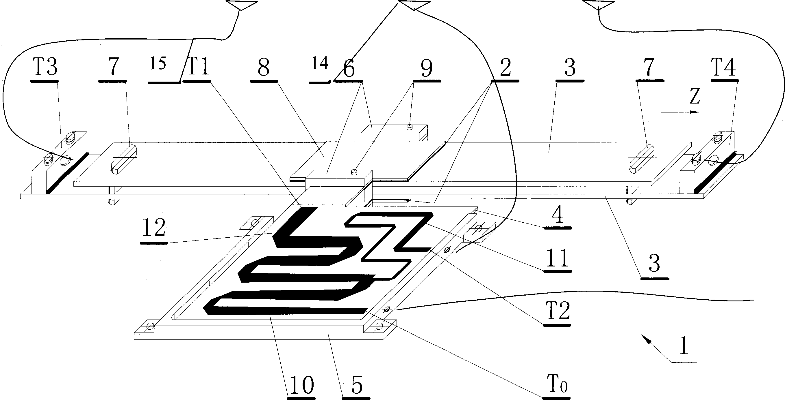
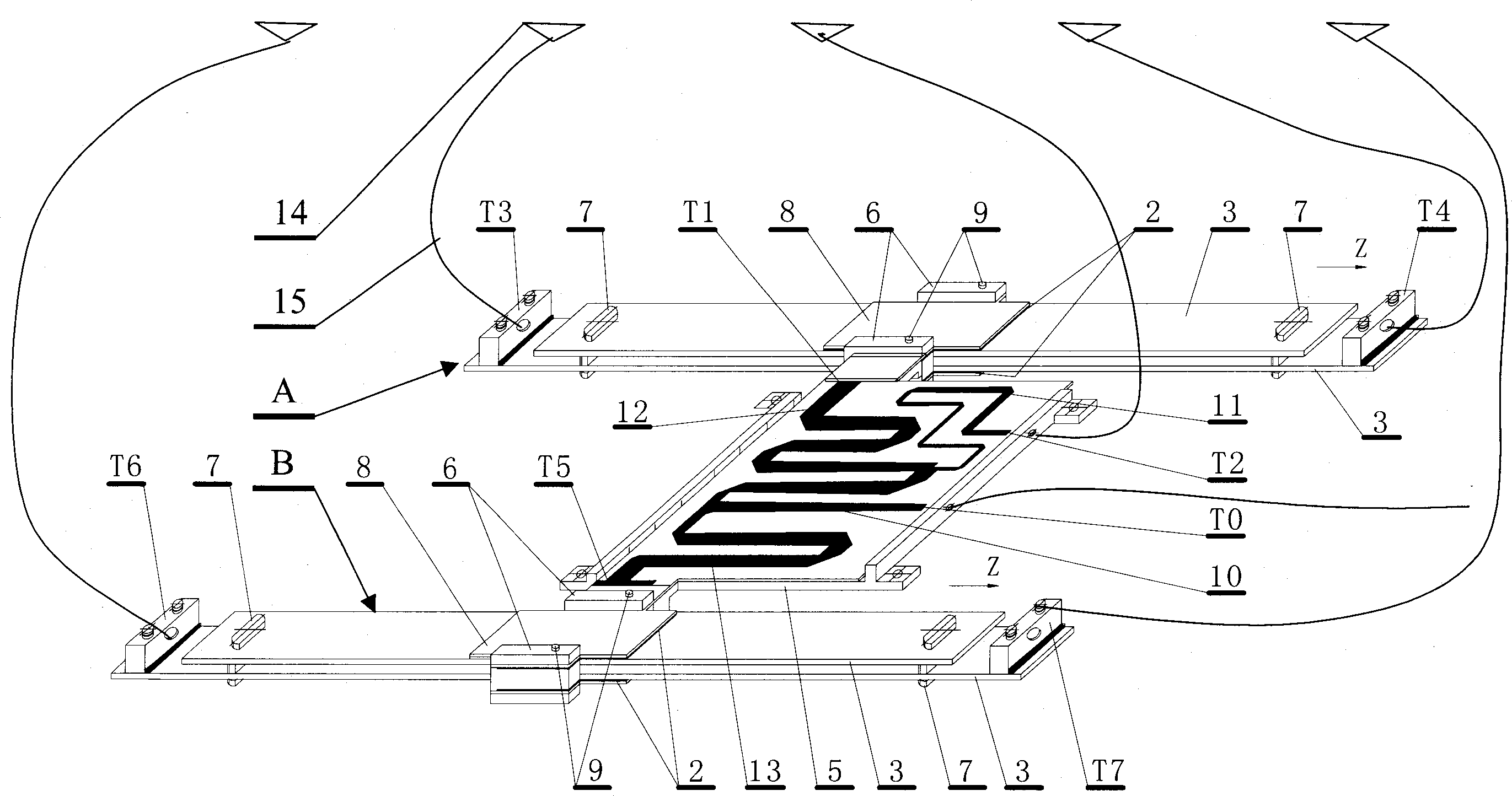
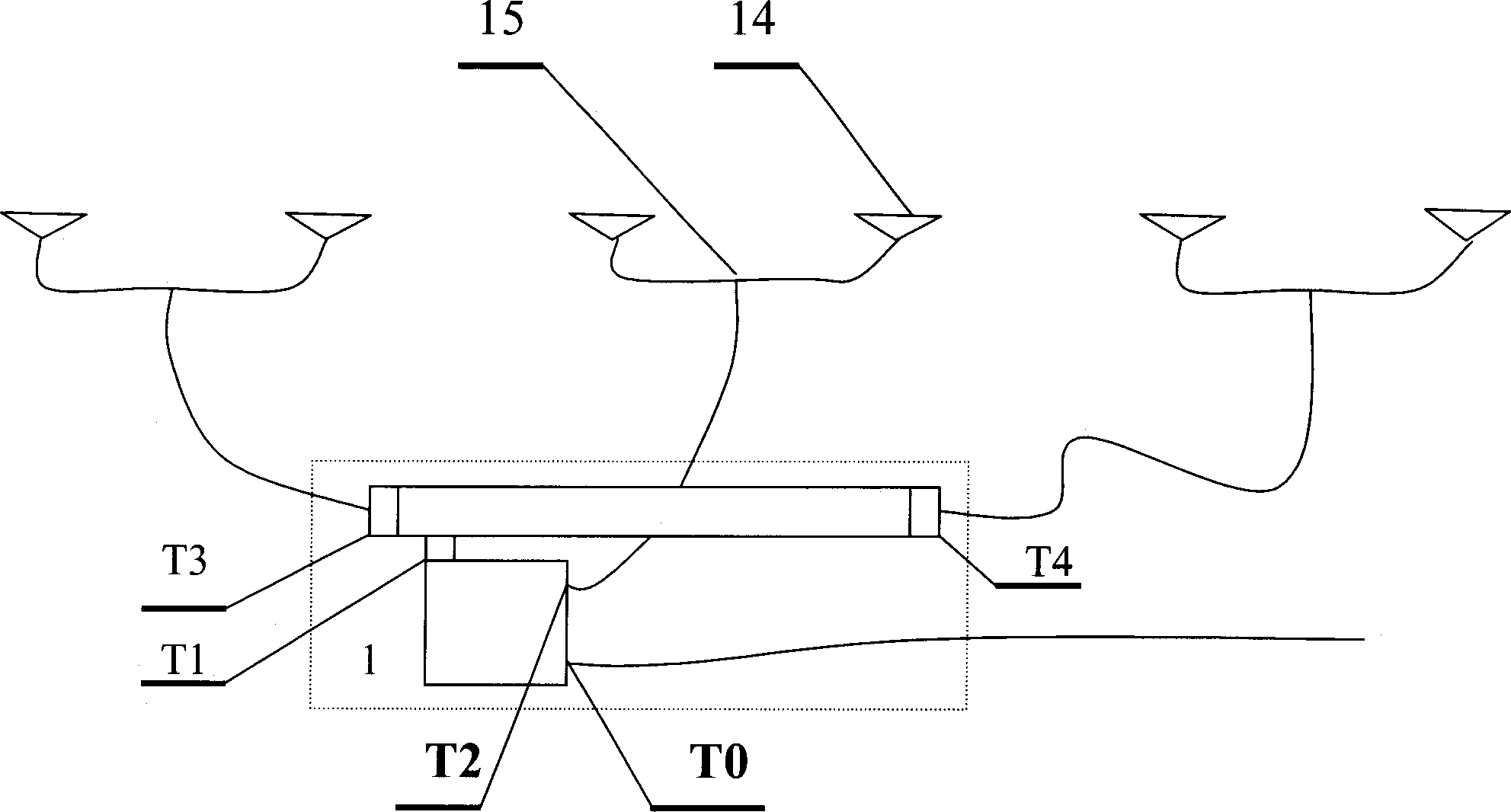
[0030] see figure 1 , the continuously adjustable phase shifter 1 of the present invention is mainly composed of a sliding plate 3 , a transmission line plate 4 and a coupling plate 8 . Slider 3 is composed of upper and lower pieces, both ends are supported and fixed by dielectric block 7, forming a characteristic impedance of Z 0 The two upper and lower parallel transmission lines of the upper and lower sliders are fixed with output terminals T3 and T4 at both ends of the lower slider 3 (or upper slider 3) to communicate with Z 0 coaxial connection. The coupling piece 8 is a "middle" shape structure composed of upper and lower pieces, and is made of 1mm thick copper plate. The two coupling pieces 8 and the dielectric piece 2 are supported by a pair of dielectric clamps 6 and locked by a dielectric pin 9. fixed in parallel to the outside of the upper and lower sliding plates 3, forming a characteristic impedance of Parallel line transmission line, and the side length is p...


PUM


Abstract

This invention provides a continuous-adjustable phase shifter containing a dielectric plate, a sliding plate, a coupling plate, a transmission-line board, among which the sliding plate is to form an air microstrip transmission line by two up-and-down strips, the coupling plate is to form a parallel transmission line by two up-and-down symmetrical metal plates and the dielectric plate fixed by a clip block at the outside of the sliding plate by use of the transition meander line microstrip structure connected with metal plate. The transmission line board decomposes the input radiation signal To to at least two routes of output signals and distributes the power at will to connect one of the routes to both ends of the sliding plate, then to send them to each radiation unit respectively afterphase shift, and another route is connected directly to the radiation unit.

Description

Technical field: [0001] The invention relates to an antenna component, in particular to a continuously adjustable phase shifter. The continuously adjustable phase shifter is especially suitable for array antennas that scan beams and change the shape of side lobes. Background technique: [0002] As we all know, the phase shifter is a key component to change the beam scanning of the array antenna. The phase shifters of various structures used in the existing antenna arrays all have defects in different degrees. For example, the Chinese patent 96193925.7 shown in Fig. 7 is an antenna array composed of three elements. The phase shifter of the antenna array is composed of a dielectric microstrip plate 16 , a dielectric sliding plate 17 and a metal base plate 18 . Microstrip lines 19 and branch lines 20 are engraved on the dielectric microstrip plate 16 . When the dielectric sliding plate 17 moves along the A direction, the signal transmission rate in the microstrip curve sect...

Claims


Application Information

Patent Timeline
Patent Type & Authority Applications(China)
IPC IPC(8): H01P1/18H01Q3/32
Inventor 谢华治
Owner XIAN HAITIAN ANTENNA TECH CO LTD
Learn More