Molecular beam source apparatus for film deposition and method for depositing film by molecular beam

A technology of molecular beam deposition and thin film deposition, applied in chemical instruments and methods, ion implantation plating, crystal growth, etc., can solve problems such as material utilization rate decline, thin film defects, uneven temperature, etc.

Inactive Publication Date: 2003-01-29
CHOSHU IND
View PDF0 Cites 15 Cited by
  • Summary
  • Abstract
  • Description
  • Claims
  • Application Information

AI Technical Summary

Problems solved by technology

Therefore, not only the utilization rate of the material is reduced, but also the defects of the film are easily caused by the uneven temperature.

Method used


Image

  • Molecular beam source apparatus for film deposition and method for depositing film by molecular beam
  • Molecular beam source apparatus for film deposition and method for depositing film by molecular beam
  • Molecular beam source apparatus for film deposition and method for depositing film by molecular beam

Examples


Embodiment Construction

[0017] Embodiments of the present invention will be described in detail below with reference to the drawings.

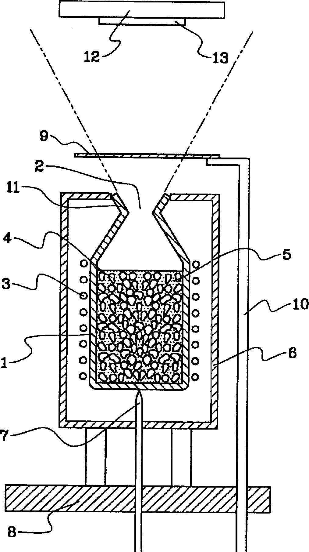
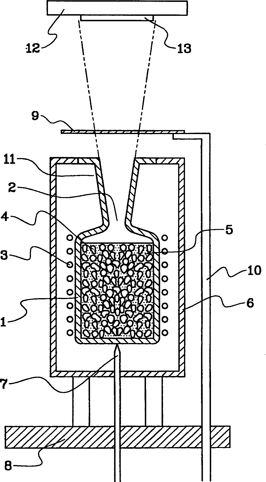
[0018] figure 1 A molecular beam source device for thin film deposition according to one embodiment of the present invention is schematically shown. Such as figure 1 As shown, a crucible 1 having a steam discharge port is provided at the upper end, and a heater 3 for heating an evaporation material 5 inside the crucible 1 is provided around the crucible 1 . The crucible 1 is made of a thermally and chemically stable material, for example PBN as described above. The portion of the vapor discharge port 2 of the crucible 1 shown in the figure has a tapered shape, and a tapered trumpet-shaped intake portion 11 is formed on the upper end side thereof. The body part below the steam outlet 2 of the crucible 1 containing the heat transfer medium 4 and the evaporation material 5 described later is cylindrical.

[0019] A reflector 6 that reflects the heat of the heater 3 ...


PUM


Abstract

A molecular beam epitaxy effusion cell, in which effusion material 5 is heated to melt down to be evaporated, so as to generate vapor molecule for growth of a thin film thereof upon a solid body surface, comprises: a crucible 1 for containing the effusion material 5 therein; and a heating means for heating the effusion material 5 contained within the crucible 1, wherein in the crucible 1 is contained heat conduction medium 4, being stable thermally and chemically and having heat conductivity higher than that of the effusion material 5, such as of pyrolytic boron nitride (PBN), together with the effusion material 5.

Description

technical field [0001] The present invention relates to a molecular beam source device for thin film deposition and a method of molecular beam deposition thin film which are used to produce evaporated molecules for forming a thin film on a solid surface by heating the evaporation material and melting the evaporation material. Molecular beam source devices for evaporation of electroluminescent materials etc. and methods for molecular beam deposition of thin films. Background technique [0002] A thin film deposition device called a molecular beam epitaxy device, places a substrate such as a semiconductor wafer in a vacuum chamber that can be decompressed in a high vacuum, and while heating it to the required temperature, directs a molecular ray source device such as Kunudsen toward the substrate. Thin film formation of the sheet is placed on the sheet, and the evaporation material in the crucible of the molecular beam source device is heated to melt and ev...

Claims


Application Information

Patent Timeline
Patent Type & Authority Applications(China)
IPC IPC(8): C30B23/08C23C14/24C30B23/02C30B23/06H01L21/20H01L21/203
CPCC23C14/24C30B23/02C30B23/066C30B29/54C30B29/58H01L21/20
Inventor 水上时雄斋藤建勇城户淳二
Owner CHOSHU IND
Why Eureka
Try Eureka