
Laser ranging method and system

A technology of laser ranging and laser signal, which is applied in the field of laser ranging and can solve the problems of increasing measurement time and so on.

Inactive Publication Date: 2003-03-19
TSINGHUA UNIV
View PDF0 Cites 19 Cited by
  • Summary
  • Abstract
  • Description
  • Claims
  • Application Information

AI Technical Summary

Problems solved by technology

One way to improve the measurement accuracy is to take the average of multiple measurements. In general, the measurement accuracy can be improved by N 1 / 2 times, but the corresponding measurement time is also increased by N times

Method used


Image

  • Laser ranging method and system
  • Laser ranging method and system
  • Laser ranging method and system

Examples


Embodiment Construction

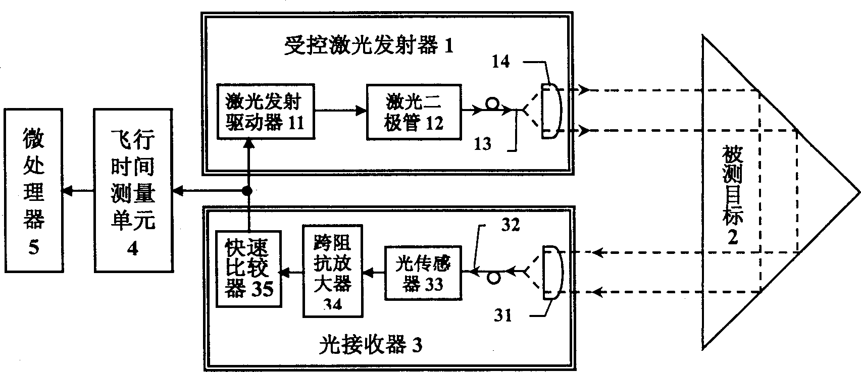
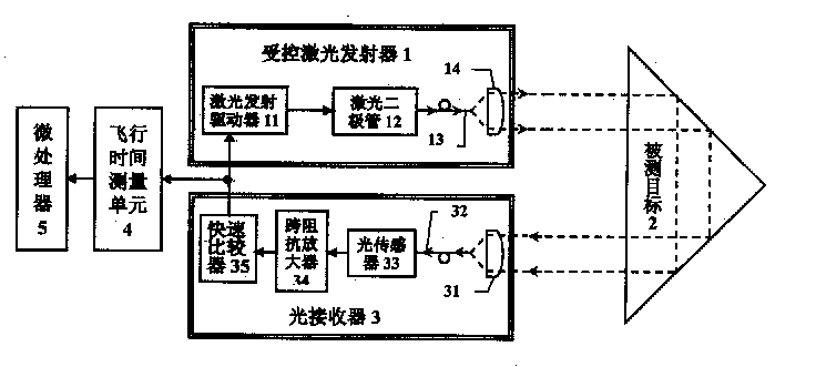
[0018] exist figure 1 Among them, 1 is a controlled laser emitter, which contains: a laser emitting driver 11, which drives a laser diode 12 to emit laser signal light, and this laser signal light is introduced into a lens 14 through an optical fiber 13 and projected onto the measured target 2; Receiver 3, which guides the laser signal reflected from the measured target 2 into the optical fiber 32 through the lens 31, and leads it to the optical sensor 33. The laser signal detected by the optical sensor 33 is amplified by the transimpedance amplifier 34 and converted into a voltage signal for transmission. To the voltage fast comparator 35, when the voltage signal received by the voltage fast comparator 35 is greater than its reference voltage, a light control signal will be output, otherwise it will output a no light control signal, and the signal will be high or low with the output level It means that the above-mentioned control signal is transmitted to the laser emission dr...


PUM


Abstract

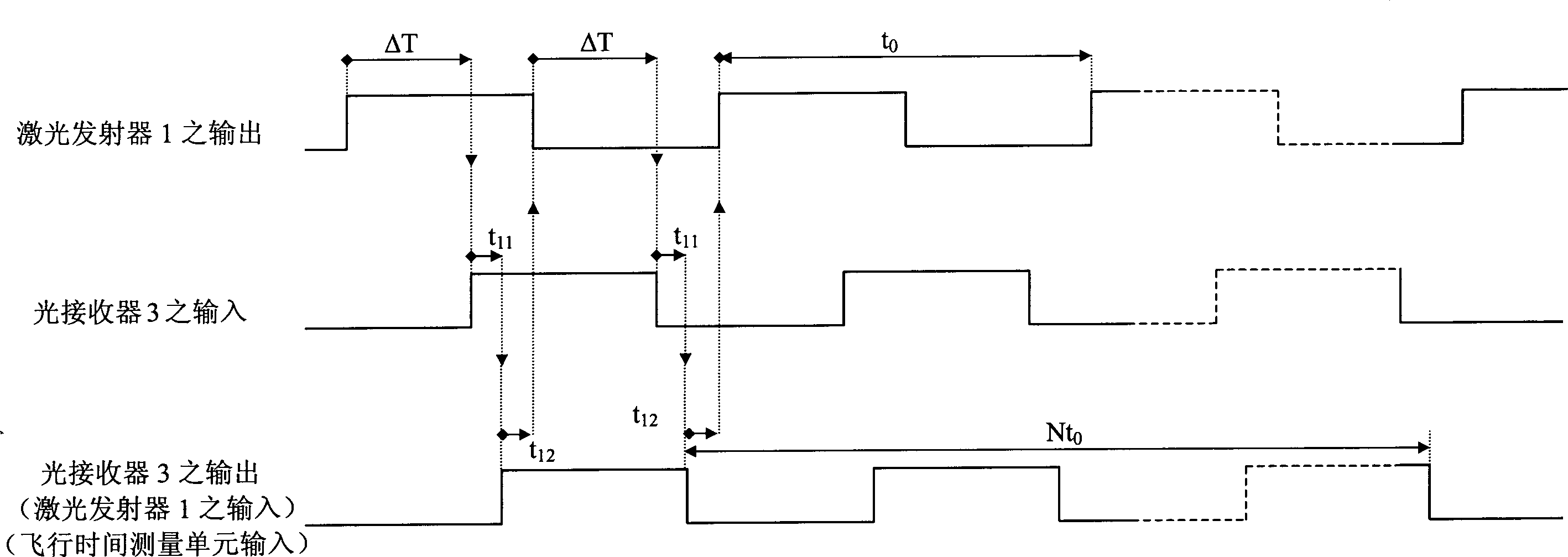
The present invention relates to laser ranging technology. In a photoelectronic signal oscillation loop comprising controlled laser emitter, measured target and optical receiver connected successively and under the control of the optical receiver, photoelectronic signal oscillation cycle of laser output yes-no-yes and stable photoelectronic signal circulation are formed in the controlled laser emitter, and thus the range may be obtained. The oscillation circuit makes it possible for continuous determination of N cycles, and the average value in the N cycles is obtained with the flying time measuring unit and the microprocessor to raise the measurement precision. Meanwhile, the present invention has shortened total measurement time.

Description

technical field [0001] A laser ranging method and a system thereof belong to the technical field of laser ranging. Background technique [0002] The basic principle of laser ranging is to calculate the time-of-flight (Time-Of-Flight) required for the laser signal light to be emitted from the rangefinder, irradiated on the target, and then reflected back to the optical sensor element of the rangefinder. )ΔT; using this flight time ΔT, the distance D between the rangefinder and the target can be directly estimated (if the air refractivity is not considered, the flight time ΔT is approximately equal to twice the distance 2D divided by the speed of light). However, since the laser signal travels at the speed of light, and the speed of light is a maximum value, when the accuracy of the distance D is to reach 1mm, the measurement accuracy of the flight time ΔT needs to reach 6.7ps (10 -12 Second). Therefore, how to accurately and quickly measure the flight time ΔT is the key tec...

Claims


Application Information

Patent Timeline
IPC IPC(8): G01S17/08
Inventor 陈千颂杨成伟霍玉晶
Owner TSINGHUA UNIV
Learn More