High-voltage discharge lamp and its manufacture

A high-pressure discharge lamp and manufacturing method technology, applied in the manufacture of discharge tubes/lamps, discharge lamps, gas discharge lamps, etc., can solve the problems of different thermal expansion coefficients, insufficient bonding force, etc., to prevent cracks, increase bonding force, The effect of suppressing cracking

Inactive Publication Date: 2003-04-02
PANASONIC CORP
View PDF3 Cites 10 Cited by
  • Summary
  • Abstract
  • Description
  • Claims
  • Application Information

AI Technical Summary

Problems solved by technology

[0009] However, although the lamp disclosed in Japanese Unexamined Patent Application Publication No. 2001-118542 has an improved withstand voltage during the lighting period, the joining force is insufficient due to the difference in coefficient of thermal expansion of the sealing portion between the coil member and the sealed tube portion.

Method used


Image

  • High-voltage discharge lamp and its manufacture
  • High-voltage discharge lamp and its manufacture
  • High-voltage discharge lamp and its manufacture

Examples


Embodiment approach 1

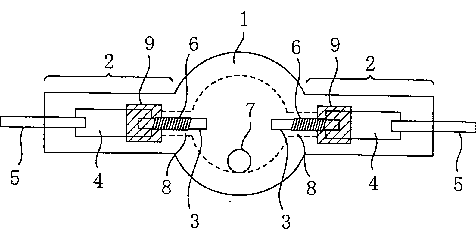
[0073] figure 1 The simulation shows the structure of the high-pressure discharge lamp according to Embodiment 1 of the present invention. In addition, a high-pressure discharge lamp is a discharge lamp whose internal pressure is 1 atmosphere or more when emitting light. A high-pressure discharge lamp is generally called a HID lamp (high-intensity lamp), and examples thereof include a high-pressure mercury lamp and a metal halide lamp.

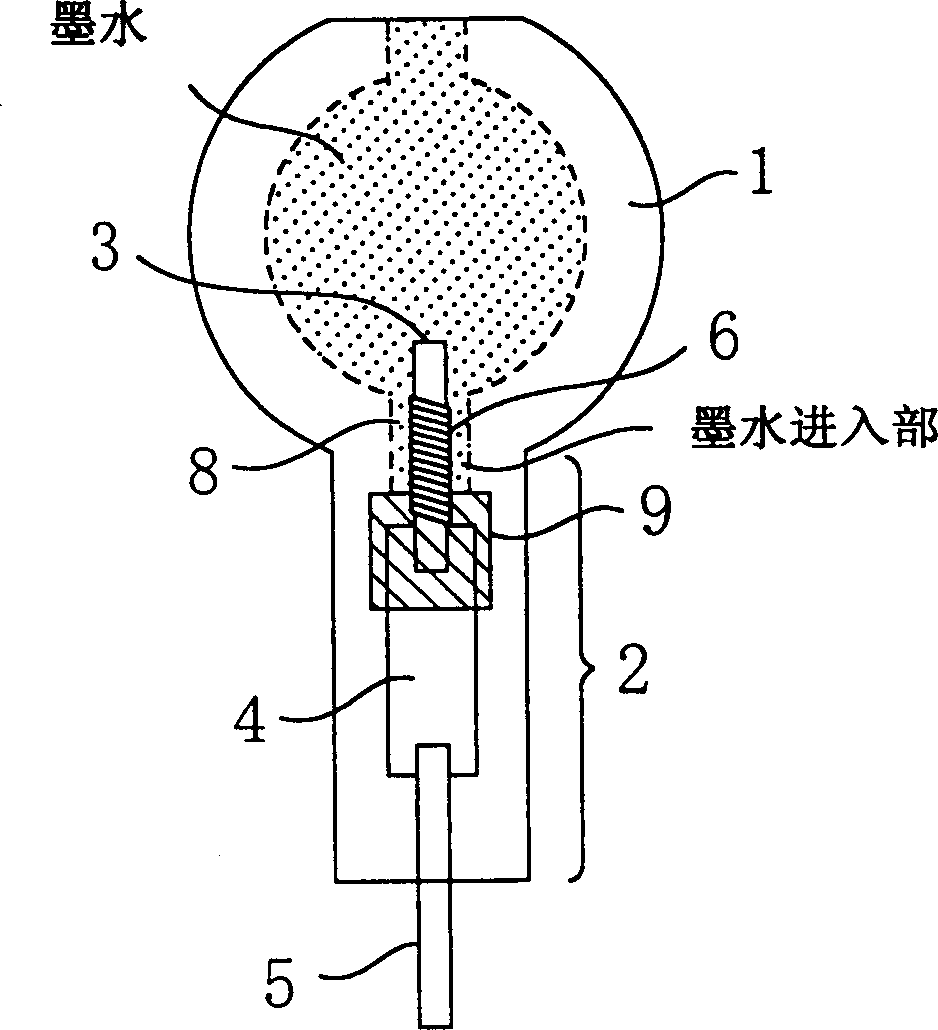
[0074] figure 1 The shown high-pressure discharge lamp consists of a light-emitting part 1 and a container (hereinafter sometimes referred to as "tube") constituted by side tubes 2 extending from both sides of the light-emitting part 1 . The main component of the material constituting the container is quartz (more specifically, quartz glass). At least mercury 7 is sealed in the light emitting unit 1 . and, figure 1 The side tube 2 of the high pressure discharge lamp shown in , has a portion (sealing portion) that maintains the airtightnes...

Embodiment approach 2

[0109] Next, a method of manufacturing the lamp according to Embodiment 1 described above will be described with reference to the drawings.

[0110] Figure 8 A tungsten coil 6 welded to the electrode rod 3 is shown. The tungsten coil in this embodiment has a diameter of about 60 μm and is wound with a winding inner diameter of about 0.25 mm. The total length of the tungsten coil 6 is about 3 mm.

[0111] The tungsten coil 6 is inserted into the electrode rod 3 for welding. Figure 9 The electrode rod 100 is shown with a tungsten coil 6 after welding. The electrode rod 3 in this embodiment has an outer diameter of about 0.25 mm and a length of about 9 mm. The tungsten coil 6 is provided on the electrode rod 3 in a space about 1 mm away from the end formed by the welded portion of the metal foil 4 and the electrode rod 3 .

[0112] Figure 10 An electrode assembly member 101 used in a lamp is shown. The metal foil 4 is, for example, a foil made of molybdenum, and the met...


PUM

PropertyMeasurementUnit
softening pointaaaaaaaaaa
diameteraaaaaaaaaa
softening pointaaaaaaaaaa

Abstract

A high pressure discharge lamp includes a vessel made mainly of quartz including a luminous portion and side tube portions extending from both sides of the luminous portion; mercury enclosed in the luminous portion; a metal foil buried in each of the side tube portion; and an electrode rod, one end of which is connected to the metal foil and the other of which is extending to the luminous portion. The electrode rod has a surface area increase structure for increasing a surface area in at least a part of a portion buried in the side tube portion. A sealing portion glass containing at least one metal material selected from the group consisting of metals and metal oxides thereof is provided in a portion of the side tube portion including at least a part of the metal foil, a connection portion between the metal foil and the electrode rod and a part of the surface area increase structure.

Description

technical field [0001] The invention relates to a high-pressure discharge lamp and a method for its manufacture. Background technique [0002] As systems become smaller, high-pressure discharge lamps used in combination with light sources for liquid crystal projectors and reflectors are expected to be smaller in size and higher in brightness. [0003] In order to realize a lamp with small size and high brightness, it must be designed with a shorter arc length. However, when the arc length is shortened, in order to obtain a light source with the same brightness as before, the pressure of the substance enclosed in the lamp must be increased because the lamp current is limited by the electrodes. That is, it is desirable for the lamp to withstand high operating pressures. In particular, it is expected that the characteristics will be dramatically improved compared with the existing technology, and it will be able to withstand ultra-high working pressure of 30 MPa or more. [...

Claims


Application Information

Patent Timeline
Patent Type & Authority Applications(China)
IPC IPC(8): H01J61/30H01J9/32H01J61/36H01J61/82
CPCH01J61/822H01J61/366H01J9/323C03C3/085H01J61/30
Inventor 金子由利子高桥清堀内诚关智行一番瀬刚甲斐诚畑冈真一郎
Owner PANASONIC CORP
Why Eureka
Try Eureka