
High polymer electrolytic shape fuel cell

A polymer electrolyte and fuel cell technology, applied in the direction of solid electrolyte fuel cells, fuel cells, fuel cell grouping, etc., can solve problems such as unfavorable volume

Inactive Publication Date: 2003-04-23
PANASONIC CORP
View PDF1 Cites 14 Cited by
  • Summary
  • Abstract
  • Description
  • Claims
  • Application Information

AI Technical Summary

Problems solved by technology

Therefore, there must be a large number of fasteners such as end plates, bolts, springs, etc., which is also very disadvantageous in terms of volume.

Method used


Image

  • High polymer electrolytic shape fuel cell
  • High polymer electrolytic shape fuel cell
  • High polymer electrolytic shape fuel cell

Examples


Embodiment approach 1

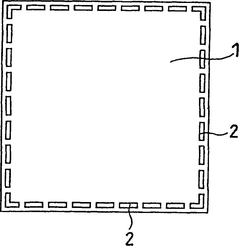
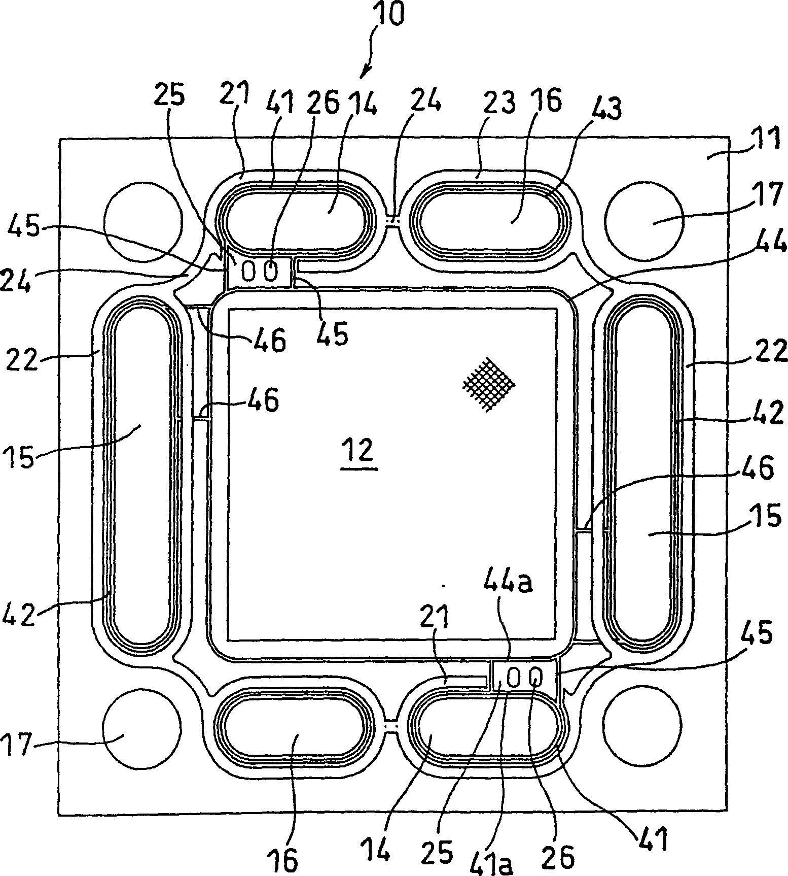
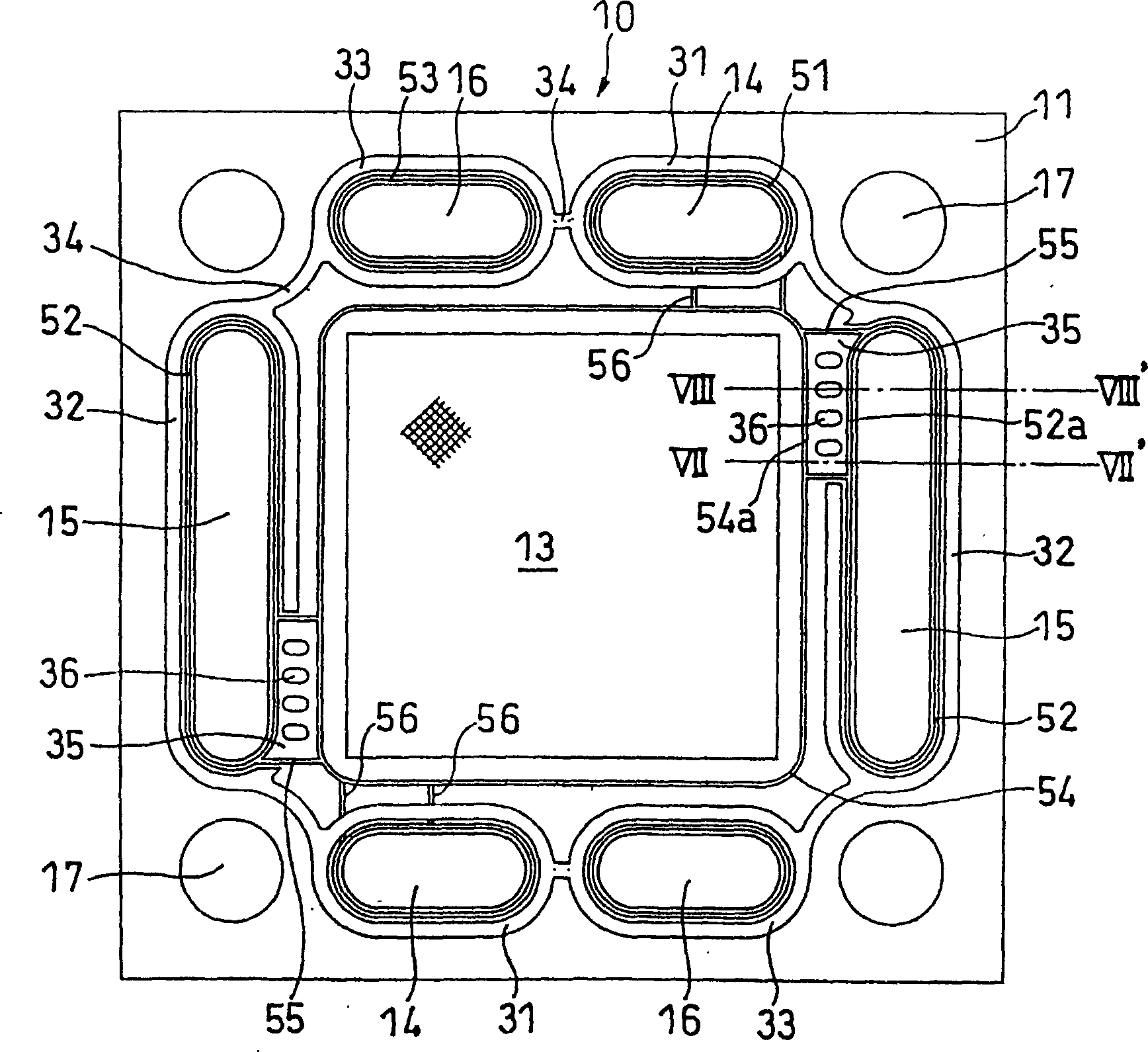
[0088] The front view of the anode side of the MEA in this embodiment is as follows figure 2 As shown, the front view of the cathode side is shown in image 3 shown. The MEA10 consists of figure 1 The polymer electrolyte membrane 1 shown is composed of a gasket 11 covering its peripheral portion, an anode 12 bonded to one side of the polymer electrolyte membrane 1 , and a cathode 13 bonded to the other side of the polymer electrolyte membrane 1 . The polymer electrolyte membrane 1 has through-holes 2 arranged in a peripheral portion. In order to cover the peripheral part including the through hole 2 part of the polymer electrolyte membrane 1, the gasket 11 is made by injection molding, and the part covering one side of the membrane 1 and the part covering the other side are between the part surrounding the edge of the electrolyte membrane and the part covering the other side. Portions of the through-holes 2 are connected to each other, supporting the membrane 1 firmly.

...

Embodiment approach 2

[0113] exist Figure 16 An example of making two seal ridges is shown in . Here, the sealing ridge 52 surrounding the manifold hole 15 on the cathode side of the gasket 11, the sealing ridge 54 surrounding the cathode, the sealing ridge 51 surrounding the manifold hole 14, and the sealing ridge 55 on both sides of the gas passage 35 are all made 2 pieces. Correspondingly, two sealing ridges provided on the anode side can also be formed respectively. In addition, one sealing ridge on the anode side may be provided at a position corresponding to the center of the two sealing ridges on the cathode side. As shown, the sealing effect can also be improved by making the sealing ridge into multiple strips.

Embodiment approach 3

[0115] Another embodiment of the portion connecting the oxidizing agent manifold hole 15 and the cathode of the gasket 11 will be described below.

[0116] In the above example, on the oxidant gas passage 35 of the gasket 11, four reinforcing ridges 36 are provided at almost equal intervals, and on the opposite side, ie, on the anode side, a continuous strip-shaped false ridge 22 is provided. The gas passage 35 is partially reinforced by these ridges 22 and reinforcing ridges 36 disposed perpendicularly intersecting them.

[0117] Figure 17 The gas passage 35 side is the same as above, but an example is shown in which the ridge 22a of the cylindrical shape is connected in the portion corresponding to the ridge 22 so that the strength becomes greater.

[0118] Figure 18 An example in which the diameter of the ridges 36a in the gas passage 35 is reduced but increased in number is shown. The ridge 22 on the cathode side remains in the band shape.

[0119] Therefore, various...


PUM


Abstract

The present invention provides a polymer electrolyte fuel cell in which neither cross leakage nor outward leakage occurs with the application of low clamping pressures. The polymer electrolyte fuel cell comprises a unit cell, the unit cell comprising: a membrane electrode assembly (MEA) (10) comprising a polymer electrolyte membrane, a gasket (11) covering the periphery of the electrolyte membrane, an anode (12) and a cathode attached to the electrolyte membrane; and conductive separator plates sandwiching the MEA therebetween. The gasket and the separator plates have a pair of manifold apertures for each of fuel gas (14), oxidant gas (15) and cooling water (16). The gasket comprises dummy ribs (21,22,23) surrounding each of the manifold apertures, and the separator plates have grooves into which each of the dummy ribs is fitted loosely such that there is a clearance therebetween. The gasket further has seal ribs (41,42,43) surrounding each of the manifold apertures, the anode and the cathode, as well as seal ribs formed on both sides of each of gas passages connecting the fuel gas manifold apertures with the anode and gas passages connecting the oxidant gas manifold apertures with the cathode. These seal ribs, except for in the gas passages, are pressed against the separator plates by clamping pressure of the cell stack to form gas sealing sections.

Description

technical field [0001] The present invention relates to a solid polymer electrolyte fuel cell, and more particularly to an improvement in the sealing structure between a gasket and a conductive separator provided on the periphery of an electrolyte membrane-electrode assembly. Background technique [0002] A solid polymer electrolyte fuel cell is most typically composed of the following parts: an electrolyte membrane-electrode assembly (MEA), an anode-side conductive separator and a cathode-side conductive separator sandwiching the above-mentioned MEA, and the anode and cathode respectively. A gas supply device for supplying fuel gas and oxidant gas, the MEA is composed of a polymer electrolytic membrane supported by a gasket whose periphery is supported by a sealing material, an anode joined to one side of the electrolytic membrane, and an anode joined to the other side of the electrolytic membrane composition of the cathode. The biggest problem with this type of fuel cell ...

Claims


Application Information

Patent Timeline
IPC IPC(8): H01M8/02H01M8/10H01M8/24
CPCH01M8/0271H01M8/1039H01M8/1023H01M8/242Y02E60/50H01M8/0276H01M8/2465H01M8/2483H01M8/02H01M8/0273H01M8/0263
Inventor 小林晋保坂正人羽藤一仁村上光竹泽干夫大西孝行
Owner PANASONIC CORP
Learn More