Microphone, diaphragm and method for making diaphragm

A manufacturing method and technology of vibrating membrane, applied in the direction of diaphragm structure, fiber vibrating membrane, transducer diaphragm, etc., can solve the problems of high material cost of vibrating membrane, limitation of thickness, increase of material loss, etc.

Inactive Publication Date: 2003-05-28
PANASONIC CORP
View PDF1 Cites 10 Cited by
  • Summary
  • Abstract
  • Description
  • Claims
  • Application Information

AI Technical Summary

Problems solved by technology

[0014] In addition, when the thin resin material 20 is used in the case of molding with a sheet-shaped material, bending or other deformation easily occurs at the frame sticking portion 5b or 28, which is pressed and fixed to the frame 13, This makes it impossible to securely attach the entire perimeter to the frame
Therefore, in the case of mass production and requiring high-quality diaphragms, it is difficult to reduce the thickness of the resin material 20 to a certain level or thinner, so that the thickness is practically limited.
In addition, since the resin material 20

Method used


Image

  • Microphone, diaphragm and method for making diaphragm
  • Microphone, diaphragm and method for making diaphragm
  • Microphone, diaphragm and method for making diaphragm

Examples


Embodiment 1

[0055] The diaphragm structure of the loudspeaker according to Embodiment 1 of the present invention will be mainly explained as follows with reference to the accompanying drawings. Here, in each figure of this embodiment, the same parts as those in the prior art are denoted by the same symbols (particularly, the magnetic circuit), and detailed description thereof will be omitted. Figure 4 is a cross-sectional view showing the structure of the loudspeaker according to the present embodiment. Figure 5 is a plan view showing the structure of the diaphragm of this embodiment. Image 6 It is a perspective view showing the appearance of the loudspeaker of this embodiment. As shown in these figures, the loudspeaker is made to include a dome-shaped diaphragm 40 in addition to a voice coil bobbin 6, a voice coil 7, a top plate 8, a yoke 9, a magnet 10, and a frame 13. Has a new cross-sectional shape.

[0056] This diaphragm 40 is made into a dome shape by melting a suitable resin...

Embodiment 2

[0061] The diaphragm structure of the loudspeaker according to Embodiment 2 of the present invention will be mainly described below with reference to the accompanying drawings. Here, in the drawings of this embodiment, the same symbols are used to designate the same parts as in Embodiment 1 and the prior art, and detailed descriptions thereof are omitted.

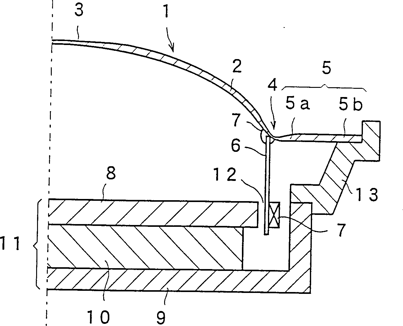
[0062] Figure 7 is a cross-sectional view showing half of the structure of the loudspeaker of this embodiment. In the description of this embodiment, and hereafter, the cross-sectional views show half of the main structure of the loudspeaker, since its structure is symmetrical about the axis. Such as Figure 7 As shown, the loudspeaker is manufactured to include a voice coil bobbin 6, a voice coil 7, a top plate 8, a yoke 9, a magnet 10, a frame 13 and a diaphragm 50, which has a new cross-sectional structure.

[0063] The vibrating membrane 50 is a dome-shaped vibrating membrane, and the cross-section of the dome is ar...

Embodiment 3

[0066] The vibrating membrane structure of the loudspeaker according to Embodiment 3 of the present invention will be mainly described below with reference to the accompanying drawings. Here, in the drawings of the present invention, the same parts as those in Embodiment 1 are denoted by the same symbols, and detailed description thereof will be omitted.

[0067] Figure 9 is a cross-sectional view showing half of the structure of the loudspeaker of this embodiment. As shown, the loudspeaker is fabricated to include a voice coil bobbin 6, a voice coil 7, a top plate 8, a yoke 9, a magnet 10, and a frame 14 and a diaphragm 60 having a new cross-sectional shape.

[0068] The vibrating membrane 60 is obtained by combining the dome-shaped vibrating membrane and the conical vibrating membrane into one body, and the cross-section of the dome-shaped vibrating membrane is Figure 9 The circular arc is shown, while the conical diaphragm includes a conical portion. The vibrating memb...


PUM

PropertyMeasurementUnit
Thicknessaaaaaaaaaa
Thicknessaaaaaaaaaa
Thicknessaaaaaaaaaa

Abstract

A diaphragm is gained by the co-molded of a dome part, a voice coil junction part, a cone part and a peripheral part through the injection mold of thermoplastic resin. The thickness of the central part of the dome is made great so that the resonance amplitude in this part becomes small. In addition, an annular rib is integrally provided to the voice coil junction part so as to increase the junction strength between the diaphragm and the voice coil bobbin. Thus, the electromagnetic driving force of the voice coil can be effectively transmitted to the diaphragm so that a loud speaker with excellent characteristics can be gained.

Description

field of invention [0001] The present invention relates to a high-frequency sound amplifier for reproducing audio signals, and to a vibrating membrane for the loudspeaker and a method for manufacturing the vibrating membrane. Background of the invention [0002] In recent years, along with the digitization of music sources to be reproduced, loudspeakers having more superior characteristics have been demanded by audio-related industries as audio output devices. Regarding the characteristics of the loudspeaker, conventional loudspeakers are required to be improved in aspects such as higher output sound level, smaller distortion and more constant frequency response. In particular, it is increasingly important to obtain a vibrating membrane of a reproduced high-frequency sound amplifier (also referred to as a tweeter) that has a great influence on the sound quality, and to establish a manufacturing method for this vibrating membrane. In conventional loudspeakers for reproducing...

Claims


Application Information

Patent Timeline
IPC IPC(8): B29C45/26B29C45/40H04R7/02H04R7/12H04R9/04H04R31/00
CPCH04R2307/029H04R7/127H04R31/003H04R2307/027H04R2231/003H04R1/24H04R2231/001H04R7/12
Inventor 武轮弘行岩佐干郎久世光一田端信也沟根信也高桥良幸小浦哲司铃木隆司土井辉夫池田清山崎裕子
Owner PANASONIC CORP
Why Eureka
Try Eureka