Miniature magnetic-driven pump

A micro-pump and magnetic energy technology, applied in the direction of pumps, pumps, machines/engines with flexible working elements, etc., can solve the problems such as the inability of micro-pumps to be applied, human body danger, etc., to achieve high safety and reliability, high safety, Stable performance

Inactive Publication Date: 2003-06-11
CHONGQING UNIV
View PDF1 Cites 2 Cited by
  • Summary
  • Abstract
  • Description
  • Claims
  • Application Information

AI Technical Summary

Problems solved by technology

But the liquid metal—mercury is a highly toxic substance. When used in the human body, it is potentially dangerous to the human body. If it breaks

Method used


Image

  • Miniature magnetic-driven pump
  • Miniature magnetic-driven pump

Examples


Embodiment Construction

[0018] Below in conjunction with embodiment the present invention is further described.

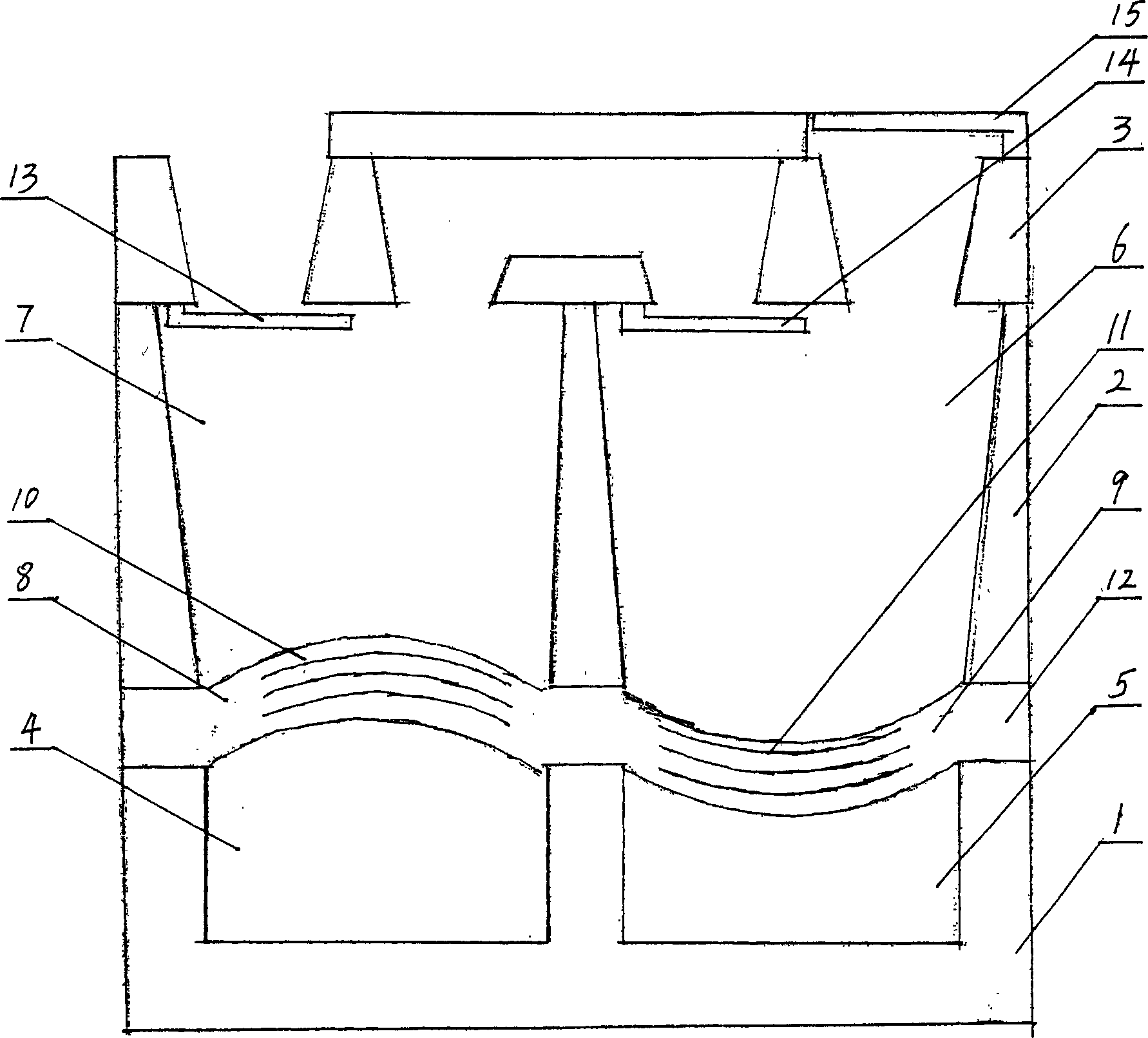
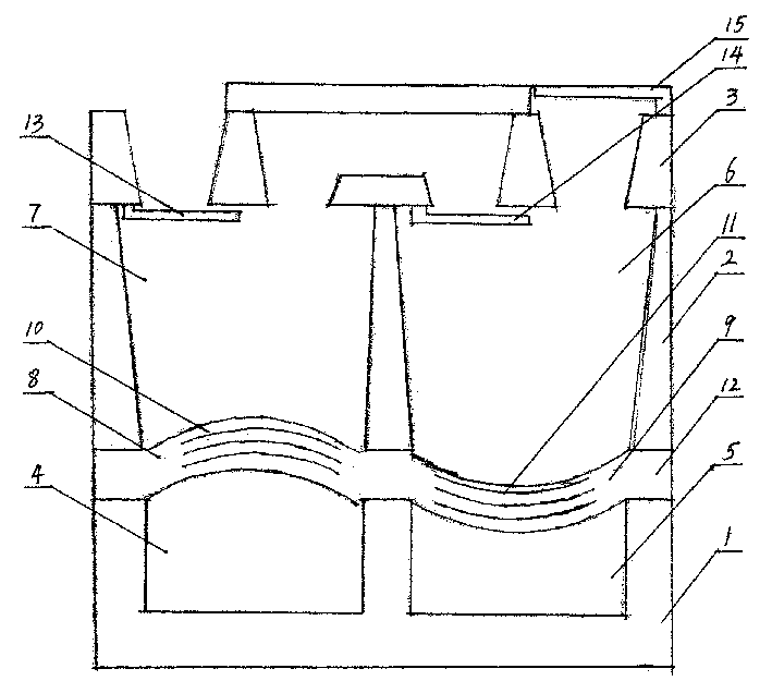
[0019] Examples of the present invention are figure 1 As shown, the overall dimensions are 6×6×6 mm. The surface structures of the base plate (1), the middle plate (2), and the top plate (3) are etched by processes such as bulk machining, surface machining, and LIGA of micromechanical surface machining. The metal copper sheet cantilever beam valve plate (13), (14), (15) is obtained by first depositing a metal copper film with a thickness of 0.1 to 100 microns on the photoresist sacrificial layer of the top plate (3), and then dissolving the sacrificial layer. of. The total thickness of the support film (12) is 10-500 microns, and the radius is 1000-4000 microns.

[0020] The micropump is divided into three layers as a whole: the upper layer is the outlet check valve (15) and the inlet check valve (13); the middle layer is the two main pump chambers (6), (7) and free surfaces (8), (9): ...


PUM


Abstract

The invention is a kind of minim pump droved by magnetism energy, it comprises a base board, a head board and a middle board which is in the middle of the other two boards, so forms four pump cavities, it has entrance and exit; it includes two free surface which are formed in the middle board; the head board has hole connected to outside; there are magnetism energy driving device in the two free surfaces to drive them, the magnetic field formed by fixed current interacts with outer magnetic field, it make the free surface change to make the volume of cavity change periodically.

Description

technical field [0001] The invention relates to a micropump with a membrane structure driven by magnetic energy, in particular to a micropump using an electromagnetic winding to drive the membrane structure. Background technique [0002] As an important micro-actuator and micro-flow control system, the micro-pump can accurately detect and control the flow rate of microliters per minute, and can be widely used in micro-release of drugs in the human body, micro-sampling of body fluids, micro-injection of fuel, cell separation, Integrated circuit cooling and microchemical analysis have important application prospects, so researchers have aroused great interest and in-depth research. At present, micropumps have been developed in a variety of structures and processing techniques. The driving principles mainly include electrostatic drive, piezoelectric drive, electromagnetic drive, thermal drive, pneumatic drive, electro-hydraulic drive, optical drive, ultrasonic drive, and shape ...

Claims


Application Information

Patent Timeline
IPC IPC(8): F04B43/04
Inventor 崔建国郑小林彭承琳刘艳皮喜田侯文生樊华彭小燕吴旭东
Owner CHONGQING UNIV
Why Eureka
Try Eureka