Ignition device for internal combustion engine

A technology for ignition devices and internal combustion engines, which is applied in the direction of engine ignition, other devices, induction energy storage devices, etc., and can solve problems such as unstable ignition coil current interruption actions

Inactive Publication Date: 2003-06-11
HITACHI AUTOMOTIVE SYST LTD
View PDF1 Cites 18 Cited by
  • Summary
  • Abstract
  • Description
  • Claims
  • Application Information

AI Technical Summary

Problems solved by technology

According to the driving method of the ignition electrode affected by this, there is a problem that the current interruption operation of the ignition coil becomes unstable.

Method used


Image

  • Ignition device for internal combustion engine
  • Ignition device for internal combustion engine
  • Ignition device for internal combustion engine

Examples


Embodiment Construction

[0014] Next, use Figure 1 to Figure 6 The configuration and operation of an ignition device for an internal combustion engine according to an embodiment of the present invention will be described.

[0015] First, use figure 1 The system configuration of the internal combustion engine ignition system of the internal combustion engine ignition device of this embodiment will be described.

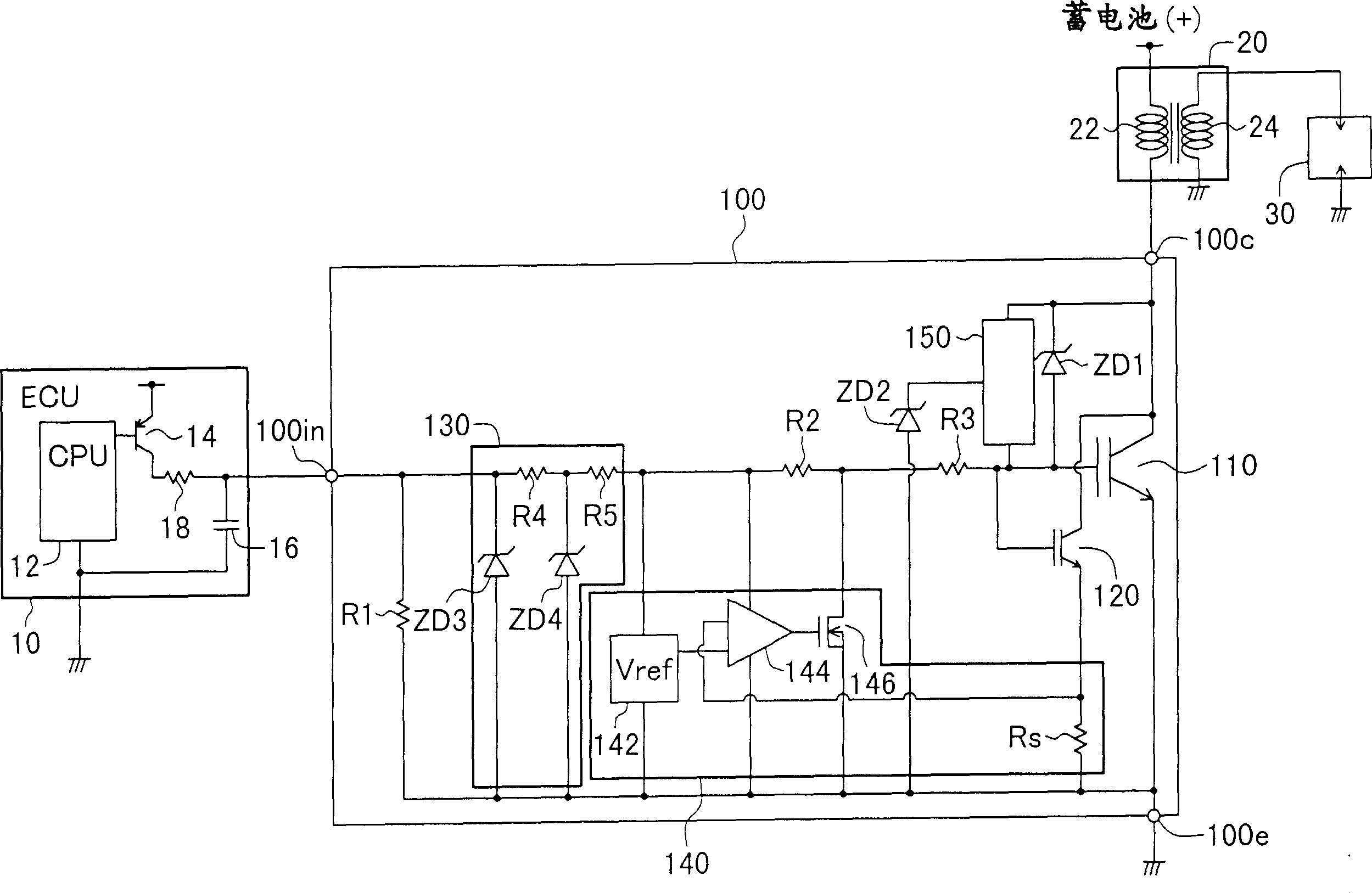
[0016] figure 1 It is a system configuration diagram of an internal combustion engine ignition system of an internal combustion engine ignition device according to an embodiment of the present invention.

[0017] The ignition system of the internal combustion engine of the present embodiment is constituted by an ignition device 100 , an ECU (Engine Control Unit) 10 , an ignition coil 20 , and an ignition spark plug 30 .

[0018] ECU 10 is composed of CPU 12 , PNP transistor 14 , capacitor 16 , and resistor 18 . PNP transistor 14 , capacitor 16 and resistor 18 constitute an output stage of...


PUM


Abstract

An ignition device for an internal combustion engine provides a stable function to interrupt the current flowing in an ignition coil A main IGBT passes or interrupts the primary current of the ignition coil depending on an input ignition control signal to generate a high voltage on the secondary dide of the ignition coil. The main IGBT and a current limiter circuit are integrated on a monolithic silicon substrate that forms insulated-gate bipolar power transistors. The collector and gate of the main IGBT are connected through a depletion IGBT and a resistor (R4) that composes a constant current supply. A Zener diode (ZD2) bypasses the current to the emitter of the main IGBT when the voltage across the resistor (R4) exceeds the Zener voltage.

Description

technical field [0001] The present invention relates to an ignition device for an internal combustion engine, in particular to an ignition device for an internal combustion engine suitable for use in an integrated control circuit. Background technique [0002] Recently, as an ignition device for an internal combustion engine, a one-chip ignition electrode (chip ignitor) in which a power IGBT (Insulated Gate Bipolar Transistor), a current limiting circuit, and an input stage protection circuit are fabricated on a single substrate is being developed. As a conventional 1-chip ignition electrode, it is considered that the structure is such that, for example, as described in JP-A-9-280147, a small constant current flows from the collector to the grid through a high-voltage constant current element, and the collector voltage ratio When the gate voltage is high, the voltage on the gate is increased, and the collector voltage fluctuation immediately after the start of the current li...

Claims


Application Information

Patent Timeline
Patent Type & Authority Applications(China)
IPC IPC(8): F02P3/04F02P3/05F02P3/055H03K17/0814H03K17/082
CPCH03K17/08148F02P3/0435F02P3/051H03K17/0828F02P3/0554H01L2224/48247H01L2924/13055H01L2924/00F02P3/04
Inventor 伊藤太加志小林良一杉浦登深津克明
Owner HITACHI AUTOMOTIVE SYST LTD
Why Eureka
Try Eureka