Dual-fuel internal cobustion engine using gas fuel at the same time

A technology of internal combustion engine and gas fuel, which is applied in the direction of internal combustion piston engine, combustion engine, engine components, etc., to achieve the effect of dual fuel and load reduction

Inactive Publication Date: 2003-07-09
NIPPON EKOSU
View PDF3 Cites 12 Cited by
  • Summary
  • Abstract
  • Description
  • Claims
  • Application Information

AI Technical Summary

Problems solved by technology

However, since the combustion air containing gaseous fuel is introduced into the combustion chamber at th...

Method used


Image

  • Dual-fuel internal cobustion engine using gas fuel at the same time
  • Dual-fuel internal cobustion engine using gas fuel at the same time
  • Dual-fuel internal cobustion engine using gas fuel at the same time

Examples


Embodiment Construction

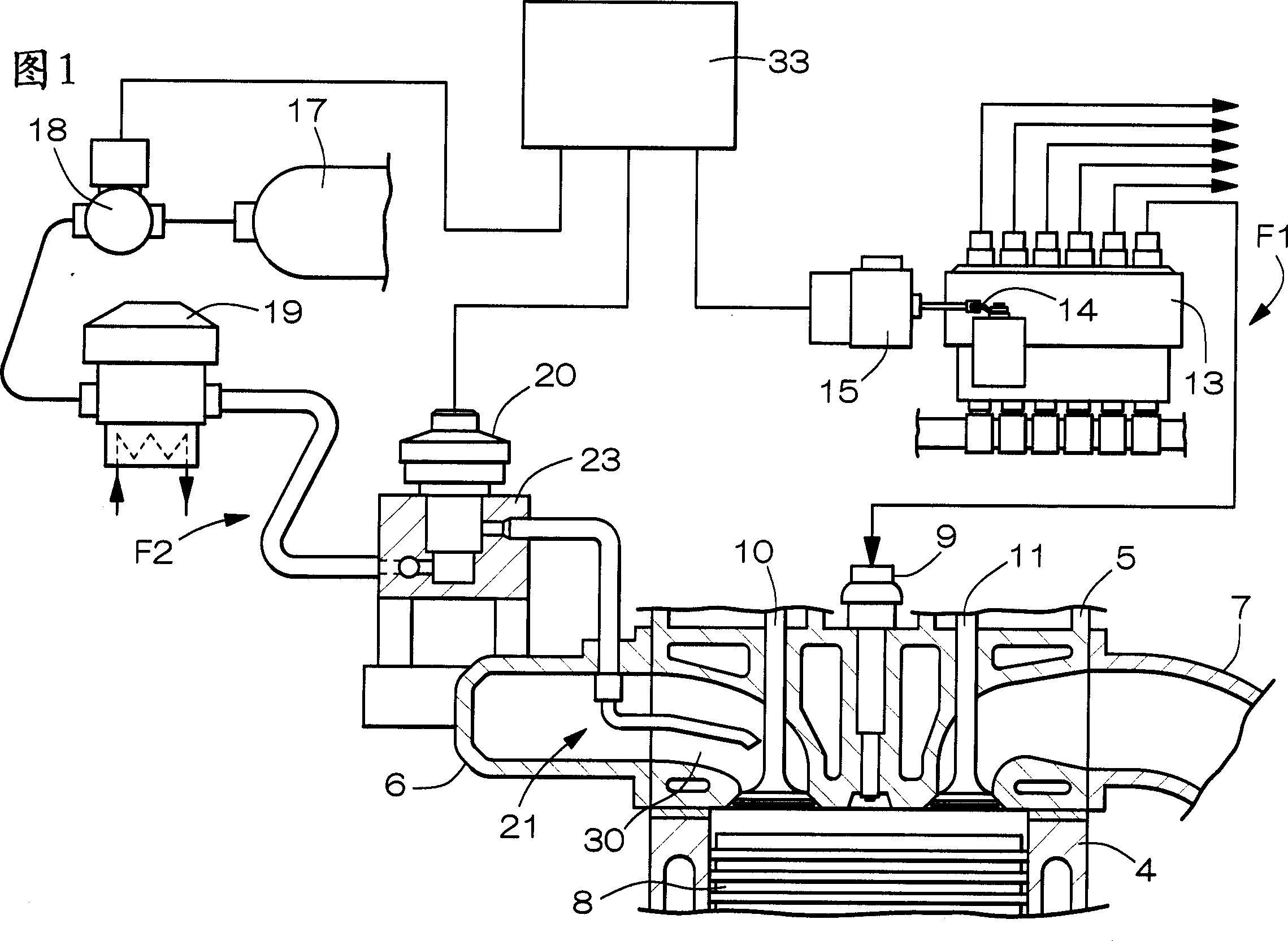
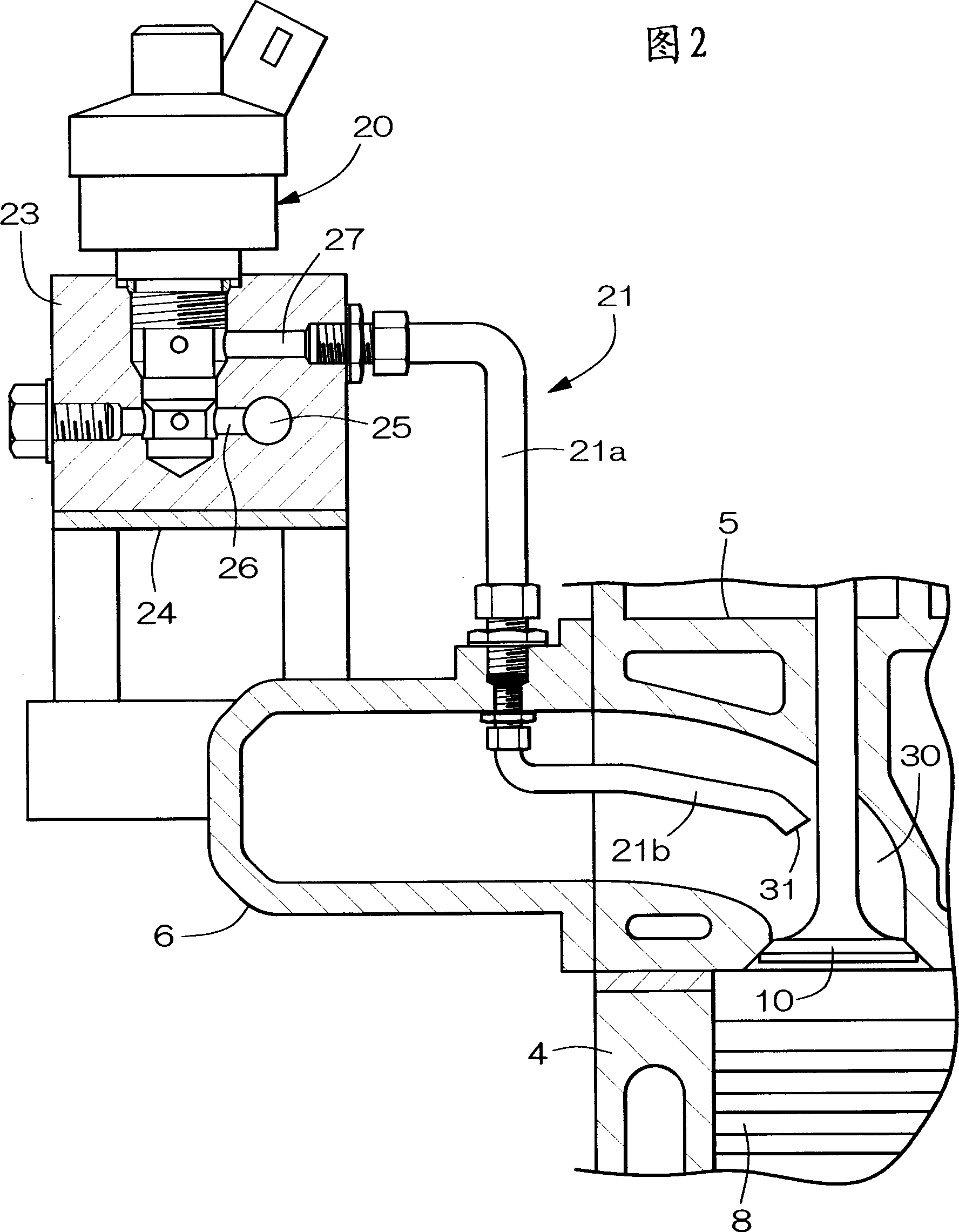
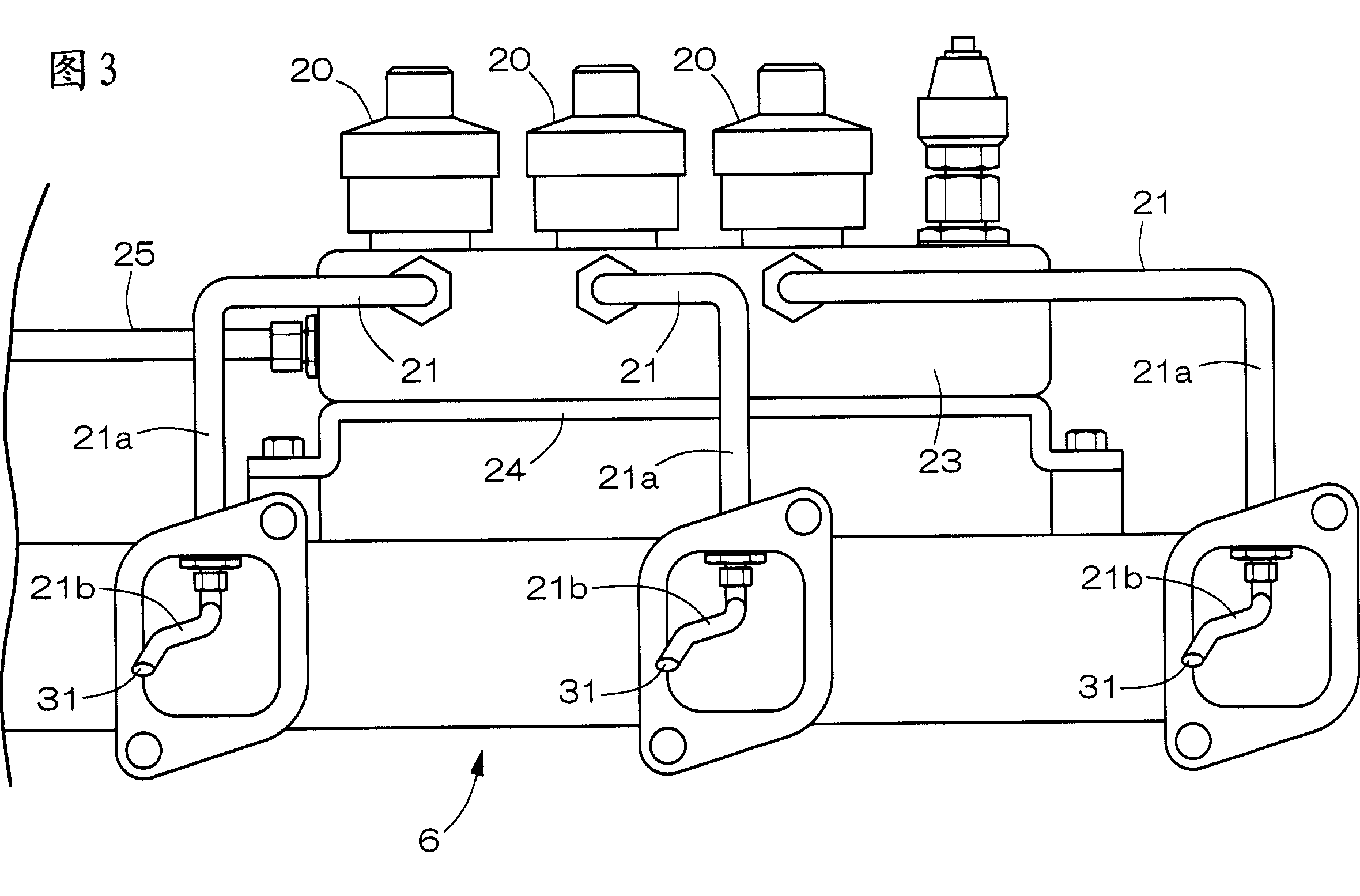
[0022] 1-5 show an embodiment of the dual fuel internal combustion engine of the present invention. In Fig. 2, the dual-fuel internal combustion engine is based on the existing known internal combustion engine (hereinafter referred to as the engine), in addition to the installed first fuel supply system F1 for supplying liquid fuel such as light oil, additional The second fuel supply system F2 for supplying gaseous fuel is additionally configured with an operation control device 3 for collectively controlling the two fuel supply systems F1, F2, control equipment, and the like. In Fig. 1, there are a cylinder block 4, a cylinder head 5, an intake manifold 6, and an exhaust manifold 7, and the cylinder head 5 is provided with a fuel injection valve 9, an intake valve 10, and a piston 8 facing the combustion chamber. And exhaust valve 11 etc. Symbol 30 is an air inlet.

[0023] The first fuel supply system F1 consists of a fuel tank and a fuel supply pump outside the figure, a ...


PUM


Abstract

A duel fuel diesel engine combining gas fuel, which comprises a first fuel supply system F1 for supplying a liquid fuel and a second fuel supply system F2 for supplying a gas fuel. The second fuel supply system F2 consists of a gas supply source 17, a pressure controller 19 for controlling the supply pressure of the gas and a gas injector 20 for injecting and supplying the gas fuel to an intake port 30. The gas injector 20 is arranged on the outer face of the engine, with its injection passage 21 having an exit 31 facing to the intake port 30. In a second intake stroke S2 after closing an exhaust valve 11, the gas fuel is injected and supplied to the intake port 30 by the gas injector 20. This makes it possible to achieve lower exhaust gas pollution by preventing the occurrence of unburnt gas or black smoke.

Description

technical field [0001] The present invention relates to a dual-fuel internal combustion engine which mixes liquid fuel and gaseous fuel in combustion air for combustion. Background technique [0002] In recent years, the regulations on exhaust gas emitted by vehicles have been increasingly strengthened. Among them, there is an increasing demand for harmless exhaust gas compared to trucks and buses equipped with internal combustion engines. In this exhaust gas countermeasure, there are methods of improving the combustion form of the engine body, reducing the emission of harmful substances such as black smoke, NOx, HC, and CO contained in the exhaust gas, and removing harmful substances by an exhaust gas purification device installed in the exhaust gas passage. In most cases, two methods are used to correspond to exhaust emission restrictions. As one of the former exhaust gas countermeasures, a dual-fuel internal combustion engine that combusts gas fuel and liquid fuel has be...

Claims


Application Information

Patent Timeline
IPC IPC(8): F02M21/02F02D19/02F02D19/08F02M21/04F02M35/104
CPCY02T10/123Y02T10/32Y02T10/12Y02T10/30
Inventor 平冈俊彦
Owner NIPPON EKOSU
Why Eureka
Try Eureka