Automatic circulating throw-in throw-off controller for low-voltage capacitor sets

An automatic switching and control device technology, applied in reactive power compensation, reactive power adjustment/elimination/compensation, etc., can solve problems such as restricting development, contact vulnerability, overvoltage, etc., to improve safety, reliability, occupation Small space and simple structure

Inactive Publication Date: 2003-07-30
中电电能监控技术有限公司 +1
View PDF0 Cites 9 Cited by
  • Summary
  • Abstract
  • Description
  • Claims
  • Application Information

AI Technical Summary

Problems solved by technology

Disadvantage: It cannot adapt to the change of reactive power load of the grid and changes accordingly
Disadvantages: There is inrush current when switching on and overvoltage when switching on. When the capacity of a single capacitor is large and the number of classifications is large, it is more serious. When switching is frequent, the contacts are vulnerable, the AC contactor is fragile, and the reliability is poor.
[0008] Disadvantages: Inrush current when switching on and overvoltage when switching on are unavoidable
Disadvantages: The main disadvantage of solid-state relays is that there is an on-state voltage drop, and high heat consumption requires corresponding cooling measures. The maximum calorific value after it is turned on is calculated as 1.5 watts per 1A of the actual passing current.
Because its heat balance is difficult to handle, it seriously restricts its development

Method used


Image

  • Automatic circulating throw-in throw-off controller for low-voltage capacitor sets
  • Automatic circulating throw-in throw-off controller for low-voltage capacitor sets
  • Automatic circulating throw-in throw-off controller for low-voltage capacitor sets

Examples


Embodiment Construction

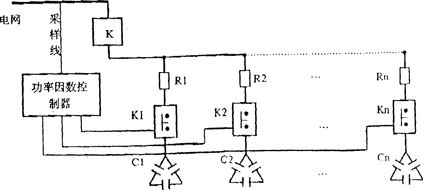
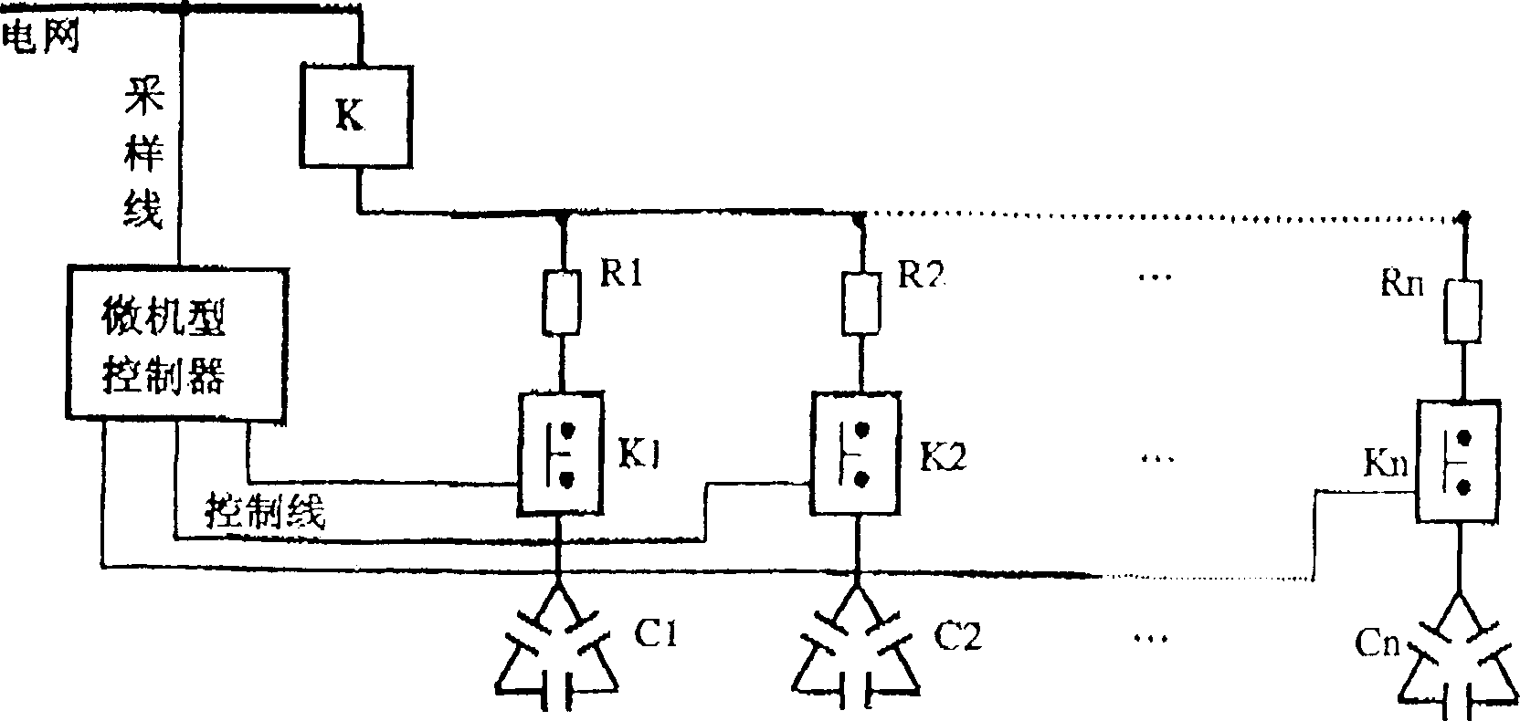
[0022] The present invention makes full use of the existing solid-state relay non-contact switch and the contact switch of the AC contactor, adopts a reasonable 1+2N scheme to make them organically combined, and then supplements it with a monitor used as a controller for the aforementioned investment. All and running requirements are realized according to sequential programming. 1+2N formula: "1" refers to a set of solid state relay non-contact switch, "N" refers to the number of capacitor groups, N=2, 3, 4..., "2N" refers to 2N AC contactors with contacts switch, see wiring Figure 5 . Switching principle: The main switch K is in the closed state under normal conditions. At this time, the controller conducts long-term online actual measurement and monitoring of parameters such as grid voltage, reactive load, power factor, etc. at the capacitor installation point.

[0023] 1. Grading investment: if a group needs to be invested (for example: C 1 When the capacitor is used, ...


PUM


Abstract

The present invention relates to automatic throw-in and throw-off controller for low-voltage power capacitor sets for reactive compensation in low-voltage power distribution network. Solid relay as non-contact switch and AC trigger as contacting switch are combined and connected and monitor as supplementary controller is used to realize programmed and stepped circulating automatic throw-in and throw-off control. The present invention has the advantages of small volume, low cost, easy maintenance, and can solve the problems of throw-in and throw-off ruch current, overvoltage and switching element heat, and raise the safety and reliability of capacitor set in running.

Description

technical field [0001] The invention relates to a power capacitor group used for reactive power compensation of an urban and rural low-voltage distribution network and a power user side, and a multi-group hierarchical cycle automatic switching control device. Background technique [0002] As we all know, the configuration of power capacitors in the power grid is a major measure for my country's power system to achieve reactive power level-by-level balance and on-site compensation. all play an important role. In particular, the reasonable allocation and operation of low-voltage power capacitors is of great significance to reduce the line loss of urban and rural distribution networks and improve the power supply level of users. [0003] At present, the switching methods of power capacitor banks used for reactive power compensation in my country's power system can be summarized into four types according to their development: [0004] 1. Manual casting: that is, using a contact...

Claims


Application Information

Patent Timeline
Patent Type & Authority Applications(China)
IPC IPC(8): H02J3/18
CPCY02E40/30
Inventor 张晋
Owner 中电电能监控技术有限公司
Why Eureka
Try Eureka