Electronic controller on board

A vehicle-mounted electronic control and controlled technology, which is applied in electrical control, engine control, fuel injection control, etc., can solve the unavoidable problems such as the decline of microprocessor control ability and responsiveness

Inactive Publication Date: 2003-09-03
MITSUBISHI ELECTRIC CORP
View PDF0 Cites 20 Cited by
  • Summary
  • Abstract
  • Description
  • Claims
  • Application Information

AI Technical Summary

Problems solved by technology

[0030] In particular, after the miniaturization and standardization of the input and output circuits of the microprocessor ...

Method used


Image

  • Electronic controller on board
  • Electronic controller on board
  • Electronic controller on board

Examples


Embodiment Construction

[0084] Implementation form 1.

[0085] (1) Detailed Description of the Configuration of Embodiment 1

[0086] Hereinafter, an in-vehicle electronic control unit according to Embodiment 1 of the present invention will be described with reference to the drawings.

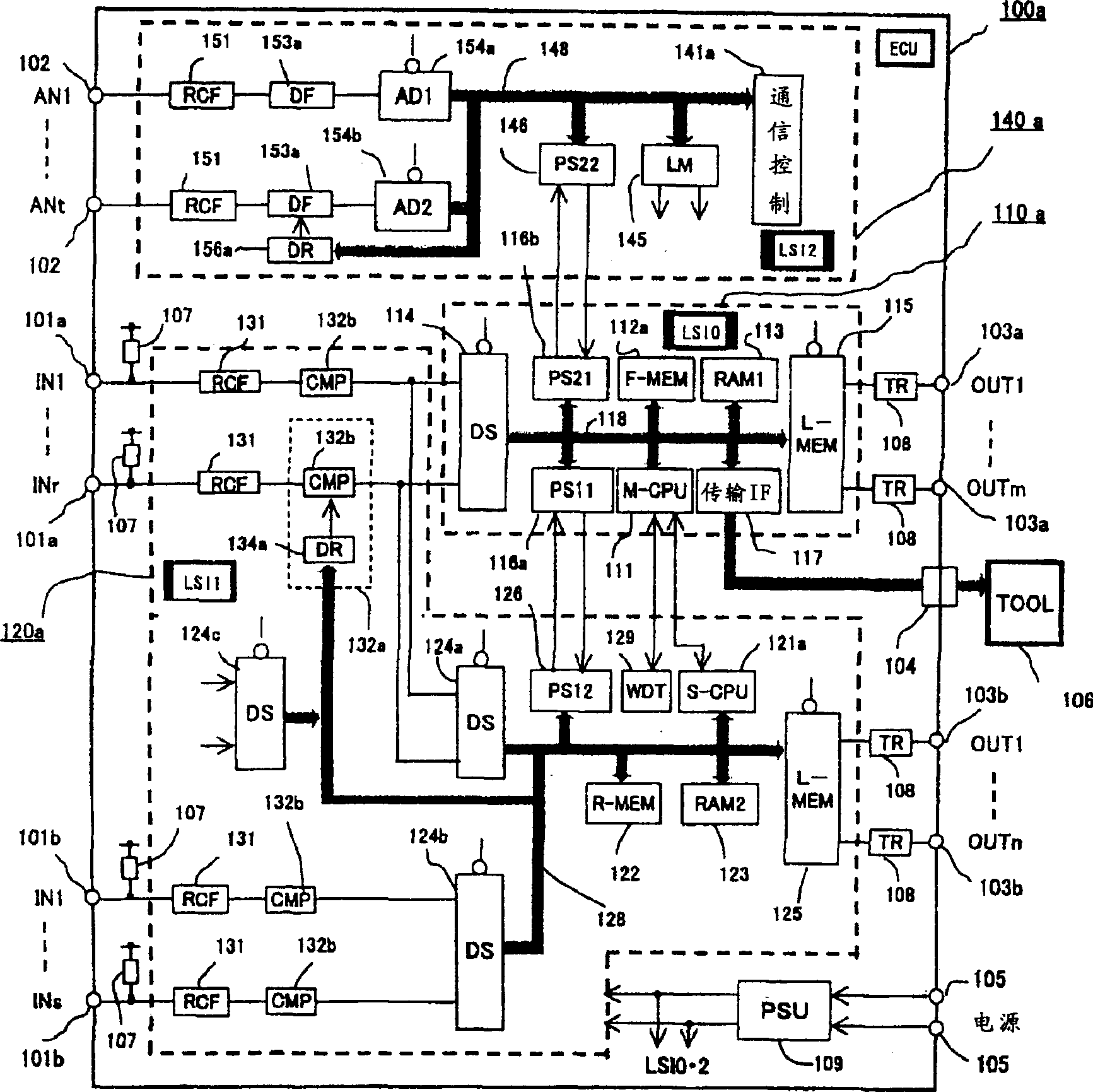
[0087] figure 1 Shown is a circuit block diagram of the vehicle-mounted electronic control unit according to Embodiment 1 of the present invention.

[0088] exist figure 1 Among them, 100a is an ECU (vehicle electronic control unit) that controls the controlled device, which is composed of a central integrated circuit device 110a, a first auxiliary integrated circuit device 120a, and a second auxiliary integrated circuit device 140a as main components, and is composed of a single circuit board .

[0089] 101a is the high-speed input signal IN1 for inputting frequent operations such as the crank angle sensor used to control the ignition timing and fuel injection timing of the engine and the vehicle speed sensor f...


PUM


Abstract

To eliminate the problem that, in the conventional car-mounted electronic control device the size of an IC diode becomes bigger because the CPU handles a considerable amount of input and output and the ECU becomes bigger to maintain a filter constant of a noise filter. The patent relates to the car-mounted electronic control device which includes a core integrated circuit device has a microprocessor. A first ancillary integrated circuit device has an indirect parallel input circuit that receives low-speed digital signals parallel, and the first ancillary integrated circuit device outputs the received digital signals serially to the core integrated circuit device. A second ancillary integrated circuit device has a multi-channel A/D converter that receives analog signals parallel and converts those into digital signals, and the second ancillary integrated circuit device outputs the digital signals serially to the core integrated circuit device. The core integrated circuit device generates control signals based on the received signals and outputs the control signals to control object devices.

Description

technical field [0001] The present invention relates to an on-vehicle electronic control device with a built-in microprocessor for fuel supply control of an automobile engine, and in particular to an on-vehicle electronic control device that improves the processing method of a large number of input and output signals, realizes miniaturization and standardization of the device, and simultaneously improves the safety of the device . Background technique [0002] Figure 14 Shown is a circuit block diagram of a conventional in-vehicle electronic control unit. [0003] exist Figure 14 Among them, 1 is an ECU (Engine Control Unit) formed on one printed circuit board, 2 is a large LSI (Integrated Circuit Device) of ECU1, and this LSI2 is a CPU (Microprocessor) 3. The nonvolatile latch memory 4 , the RAM memory 5 , the input data selector 6 , the A / D converter 7 , the output latch memory 8 , and the like are connected by a data bus 30 . 9 is a power supply assembly for supplying...

Claims


Application Information

Patent Timeline
IPC IPC(8): F02D45/00F02D41/26
CPCF02D41/26F02D41/266
Inventor 桥本光司中本胜也
Owner MITSUBISHI ELECTRIC CORP
Why Eureka
Try Eureka