Cutting tool and method of using same

A technology of cutting tools and cutting elements, applied in the fields of picks, saws and drills, it can solve the problems such as the falling off of the cutter head, and achieve the effect of excellent cutting performance

Inactive Publication Date: 2003-09-17
COMMONWEALTH SCI & IND RES ORG
View PDF2 Cites 18 Cited by
  • Summary
  • Abstract
  • Description
  • Claims
  • Application Information

AI Technical Summary

Problems solved by technology

The present inventors have found that common methods of joining the cutting bit to the tool body, such as vacuum brazing, do not always form a bond of sufficient strength and thus the bit may fall off during use

Method used


Image

  • Cutting tool and method of using same
  • Cutting tool and method of using same
  • Cutting tool and method of using same

Examples


Embodiment Construction

[0093] In the following detailed description of the preferred embodiment as shown in the accompanying drawings, like reference numerals refer to like parts.

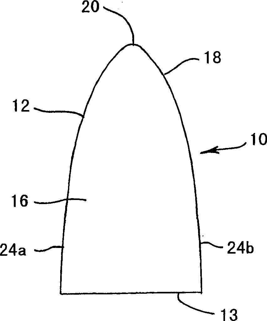
[0094] figure 1 A cross-section of a cutting element 10 is shown that includes a pointed body 12 formed from ADC. The cutting element 10 includes a base 13, an elongated mounting portion 16 adapted to be received on a support substrate of a tool body (not shown), and a cutting portion 18 having a cutting face or point 20 formed thereon. . The cutting tip 18 is oval, or bullet-shaped, while the sides 24a, 24b of the mounting portion 16 taper inwardly from the base 13 to the cutting portion 18 .

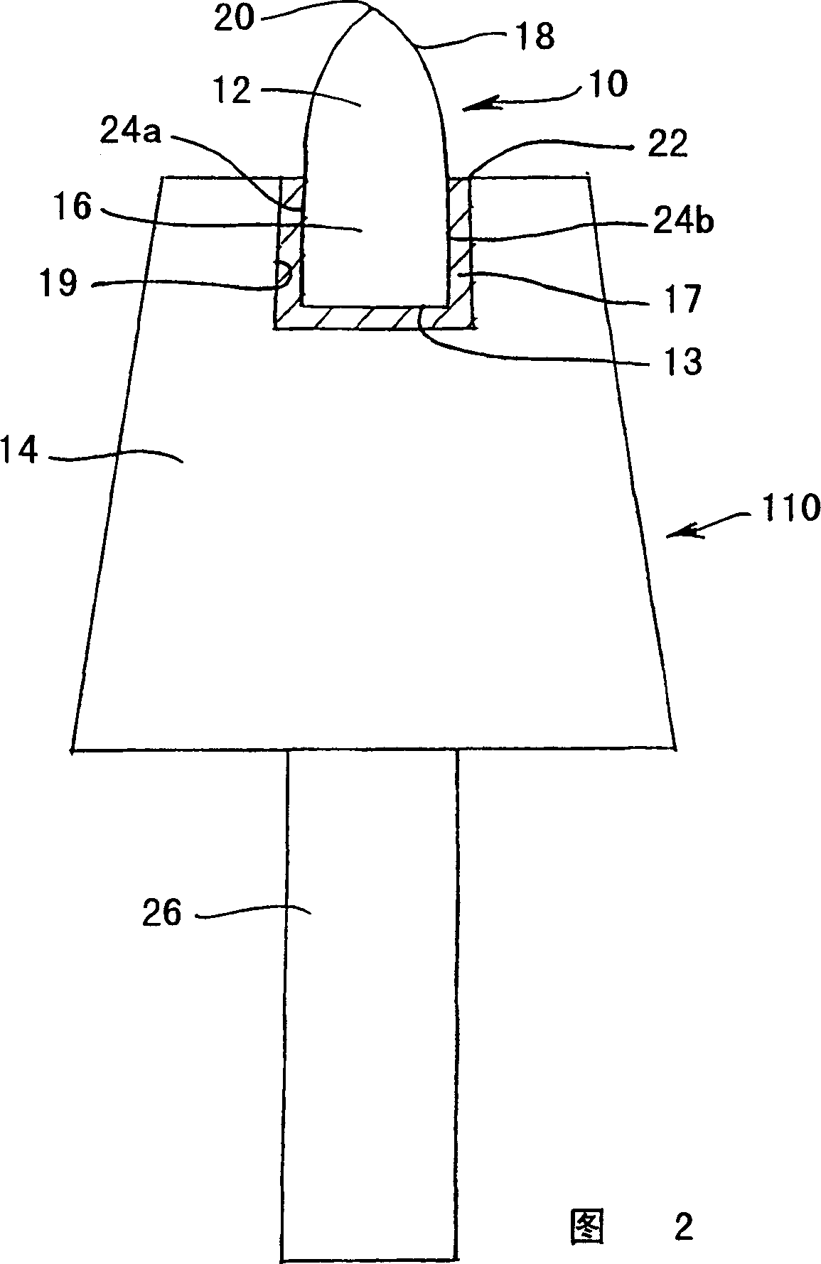
[0095] In FIG. 2 , a pick 110 is shown comprising a cutting element 10 comprising a pointed body 12 formed from ADC mounted on a pick body 14 made of steel. The cutting element 12 is included in the figure 1 The structure shown in , will not be repeated here. An elongated mounting portion 16 fits in a recess 17 on the pick b...


PUM

PropertyMeasurementUnit
strengthaaaaaaaaaa

Abstract

A cutting tool for cutting hard rock, the cutting tool including one or more cutting elements each including a pointed or chisel-shaped body including a diamond composite material including diamond crystals bonded together by a silicon carbide matrix, the each cutting element being mounted into a supporting matrix including a metal matrix composite material, such that the point or chisel edge of the each element protrudes from the matrix.

Description

technical field [0001] The present invention relates to an improved cutting tool for cutting, drilling or sawing hard materials such as rocks, stones, concrete and the like. In particular, the present invention relates to a pick, saw and drill incorporating diamond composite bits or blades, and methods of use thereof. Background technique [0002] In the process of excavating, mining, cutting, machining or drilling rock, stone, concrete and similar hard materials, machines employ various cutting tools, hereinafter collectively referred to as "cutting tools". Three widely used cutting tools are picks, saws, and drills. [0003] pick [0004] Picks are used as cutting tools in machines used in applications such as coal mining and tunneling in rock. The term "pick" (also "scraping cutter") generally refers to a pointed or chisel-shaped rock cutting tool that cuts rock by penetrating and scraping along its surface. Picks typically include a steel shank while the cobalt tungs...

Claims


Application Information

Patent Timeline
Patent Type & Authority Applications(China)
IPC IPC(8): E02F9/28E21B10/46E21B10/56E21B10/567E21C35/18E21C35/183E21D9/087
CPCE21B10/567E21C35/183E21C35/1831E21C35/188E21C35/1837
Inventor J·N·波兰德K·邦克P·E·维利斯
Owner COMMONWEALTH SCI & IND RES ORG
Why Eureka
Try Eureka