Proportional direction valve

A proportional directional valve, proportional electromagnet technology, applied in the direction of fluid pressure actuation device, servo motor assembly, mechanical equipment, etc., can solve the problems of fracture, proportional electromagnet deformation, easy oil leakage, etc., to improve the sealing environment, work The effect of low thrust and low working noise

Inactive Publication Date: 2003-10-08
NINGBO HOYEA MACHINERY MFG
View PDF1 Cites 9 Cited by
  • Summary
  • Abstract
  • Description
  • Claims
  • Application Information

AI Technical Summary

Problems solved by technology

[0003] The technical problem to be solved by the present invention is to overcome the defects that the proportional electromagnet ejector rod and its oil cavity area of ​​the existing background technology products need to withstand the control oil pressure provided by the high-pressure oil pump for a long time, which causes the proportional electromagnet to deform, easily leak oil or even break. , to provide the society with a proportional directional valve with low sealing requirements between the proportional electromagnet and the pilot valve body, small working thrust of the proportional electromagnet, and sensitive response of the pilot valve spool

Method used


Image

  • Proportional direction valve
  • Proportional direction valve
  • Proportional direction valve

Examples


Embodiment Construction

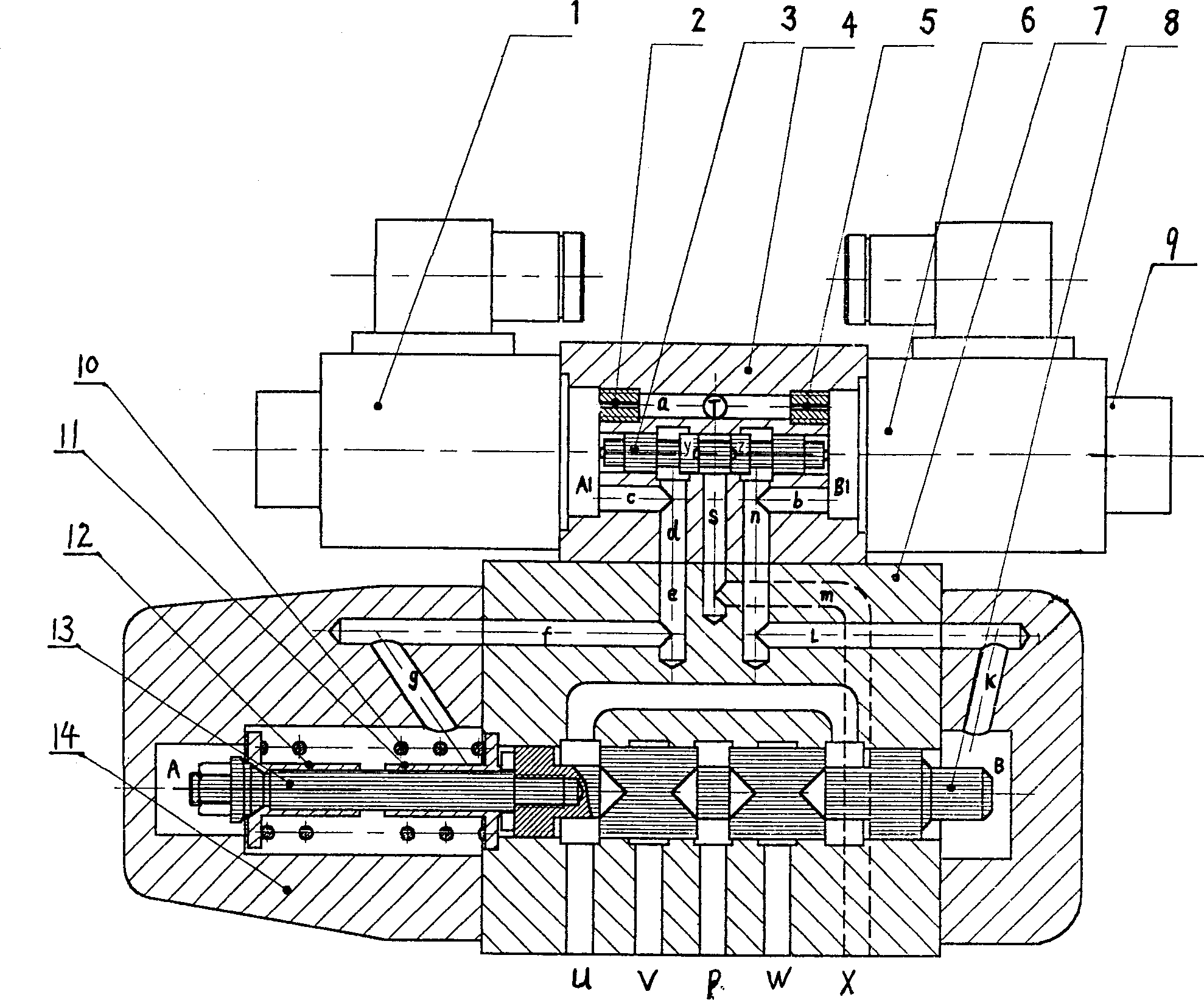
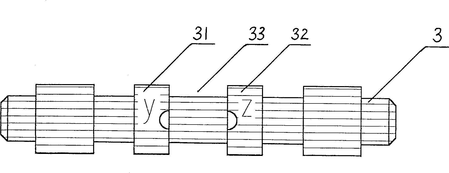
[0012] Such as figure 1 As shown, the proportional directional valve product of the present invention includes two parts, the pilot valve 9 and the main valve 14 . The pilot valve 9 includes proportional electromagnets 1 and 6 at the left and right ends, a pilot valve body 4 , and a pilot valve core 3 arranged in the pilot valve body 4 . A transverse oil passage a is arranged inside the pilot valve body 4, and a T hole communicating with the return oil of the control oil is arranged on the oil passage a. Damping screws 2 and 5 are respectively set at the ports where the transverse oil passage a enters the left and right proportional electromagnet ejector rod oil chambers A1 and B1. At the lateral position below the pilot valve spool 3, two oil passages c and b are drawn from the left and right proportional solenoid ejector rod oil chambers A1 and B1 respectively, and vertical oil passages d and n are respectively arranged at the transverse hole ends of the oil passages c and ...


PUM


Abstract

This invention discloses a proportional direction valve including a pilot valve and a main valve in which, the pilot valve includes right and left proportional magnet, a valve and a core in the valve, the main valve constitutes a main valve and a core in it characterizing in that a lateral oil channel is designed in the said pilot valve with right / left proportional electromagnetic pin-lift oil recess at both sides, a spill port at the channel midle, damping screws are set at the port of the recess. A control oil port of the main valve is connected with the control channel at the middle of thepilot valve via the oil channel, and stops at two ring under cut slots and flow-save windows are designed on two shoulders of the pilow valve.

Description

technical field [0001] The invention relates to a hydraulic transmission control component, in particular to a spool type proportional directional valve for controlling the flow by controlling the displacement of the spool. Background technique [0002] The spool type proportional directional valve generally uses a proportional electromagnet to drive the spool, and uses the principle that the input voltage or current of the proportional electromagnet is proportional to the displacement of the spool to control the flow of hydraulic oil. It is widely used in injection molding machines, In the hydraulic control system of mechanical processing equipment such as die-casting machines, extrusion machines and stretching machines. Existing typical products include the 4WRZ16 pilot control spool valve produced by German REXROTH company. This valve can form different pressure differences in the A and B chambers at both ends of the main valve, so that the main valve core can move to con...

Claims


Application Information

Patent Timeline
IPC IPC(8): F15B13/044
Inventor 凌俊杰翁振涛
Owner NINGBO HOYEA MACHINERY MFG
Why Eureka
Try Eureka