Rolled member head shape controlling method

A technology of head shape and control method, applied in the direction of tension/pressure control, etc., can solve the problems of upturning or buckling of the rolled head, affecting normal production, accidents, etc., to speed up the production rhythm, reduce the labor intensity of workers, The effect of increasing the rolling speed

Inactive Publication Date: 2003-10-29
NANJING IRON & STEEL CO LTD
View PDF0 Cites 18 Cited by
  • Summary
  • Abstract
  • Description
  • Claims
  • Application Information

AI Technical Summary

Problems solved by technology

During the rolling process, the head of the rolled piece often appears upturned or buckled down, which affects normal production and even causes accidents in severe cases.

Method used


Image

  • Rolled member head shape controlling method
  • Rolled member head shape controlling method
  • Rolled member head shape controlling method

Examples


Embodiment 1

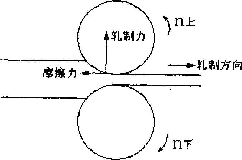
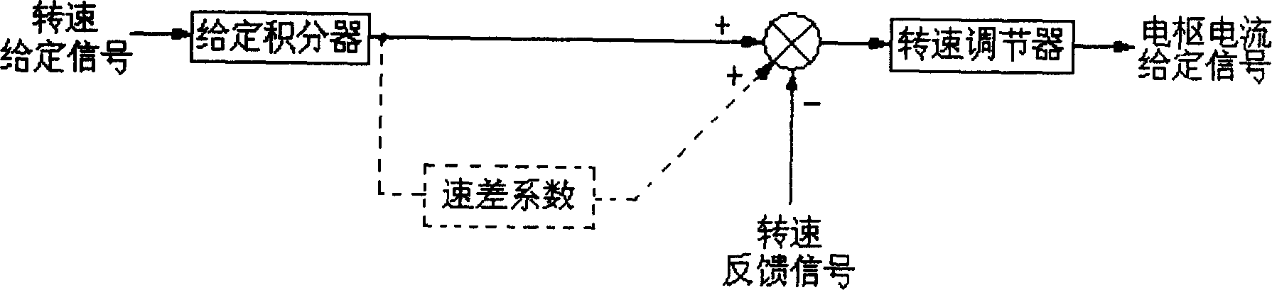
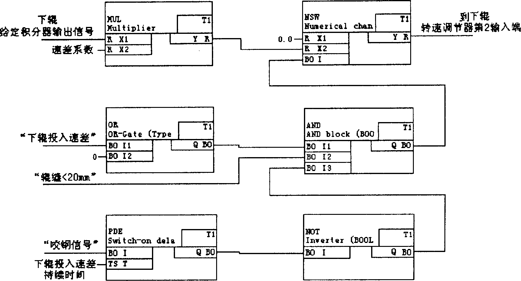
[0021] Embodiment 1 is an improved method on the basis of the first technical scheme, image 3 It is the software structure diagram, and the speed control system of the following work rolls is taken as an example. The SIMADYN D full digital control system of Siemens is used to form the main motor speed control system. Among the software function blocks used in the SIMADYN D full digital control system, X, X1, and X2 are input terminals, and the data type is real number R; Y is output Terminal, the data type is real number R; I, I1, I2, I3 are input terminals, the data type is logical quantity BO; Q is the output terminal, the data type is logical quantity BO; T is the input terminal, the data type is time TS, the unit ms; in image 3 in, corresponding to figure 2 In the dotted line, the output signal of the lower roll set integrator is multiplied by the multiplication function block MUL and the speed difference coefficient, and the corresponding speed difference setting is ...

Embodiment 2

[0022] Example 2 as Figure 4 As shown, the following work rolls are taken as an example. exist Figure 4 The MFP pulse generator function block is used in the system. When the "steel biting signal" is 1, the Q terminal of the MFP is 1, and becomes 0 after the set "lower roll input speed difference duration". When the I terminal is 0, its Q terminal is 0; as long as the I1, I2, and I3 terminals of AND are all 1, the speed difference setting is enabled, otherwise it is not enabled.

Embodiment 3

[0023] Example 3 as Image 6 shown.


PUM


Abstract

A method for controlling the head shape of the workpiece rolled by 4-roller rolling mill of middle-thickness plate is characterized by that an offset setting is applied to the rotation speed regulator of main motor for lower working rollers to change its speed, so preventing the head of workpiece from bending up or down.

Description

1. Technical field [0001] The invention relates to a method for controlling the shape of the head of a rolled piece of a four-high rolling mill for medium and heavy plates, and relates to an automatic control method in the process of metal pressure processing in the metallurgical industry. 2. Background technology [0002] In the process of rolling steel plates with a four-high rolling mill for medium and heavy plates, the speed of the upper and lower work rolls is controlled by the main drive control system. In the transmission control system, after the main transmission control system gets the signal, it passes through a given integrator and compares it with the speed feedback signal to form a speed deviation signal that is input to the speed regulator. After proportional integral calculation, an output signal is generated, that is, the armature current is given to fixed signal, armature current given signal and armature current feedback signal are compared to form an arma...

Claims


Application Information

Patent Timeline
Patent Type & Authority Applications(China)
IPC IPC(8): B21B37/52
Inventor 王军
Owner NANJING IRON & STEEL CO LTD
Why Eureka
Try Eureka