Soft metal screen

A soft metal and screen technology, applied in multidisciplinary fields, can solve the problems of difficult installation and handling, large screen size and high price, and achieve the effects of significant economic benefits, high resolution, and low production costs.

Inactive Publication Date: 2003-12-10
李树权
View PDF1 Cites 0 Cited by
  • Summary
  • Abstract
  • Description
  • Claims
  • Application Information

AI Technical Summary

Problems solved by technology

Although this patented technology improves the definition of projected images and subtitles, and improves the display effect and quality, it still has the problems of large screen size, heavy weight, difficult installation and transportation, and high price.

Method used


Image

  • Soft metal screen
  • Soft metal screen
  • Soft metal screen

Examples


Embodiment Construction

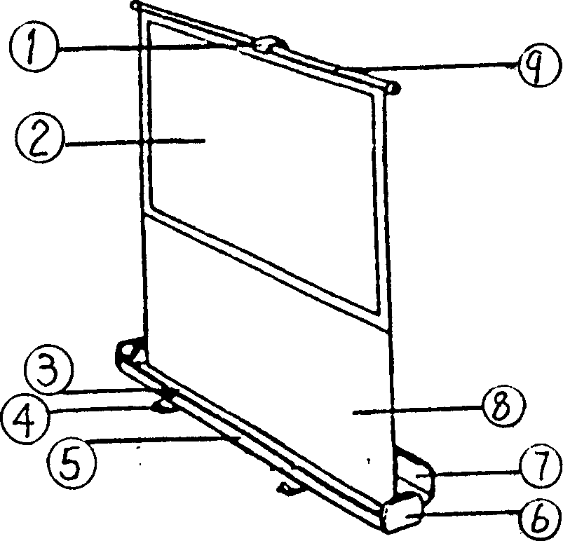
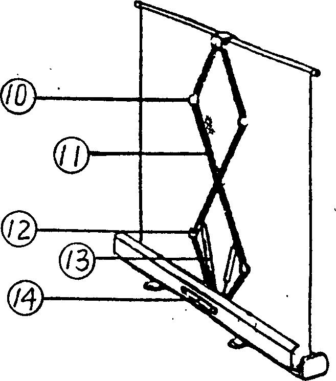
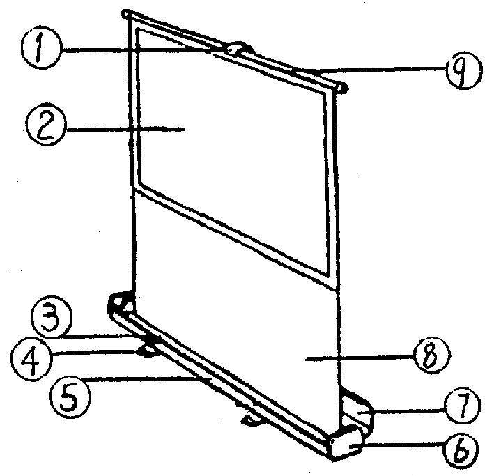
[0022] The present invention is realized like this, see figure 1 , figure 2 , below in conjunction with the accompanying drawings to do a specific description. The soft metal screen has changed from the hard metal screen, which is bulky and difficult to transport and install. It avoids problems such as small viewing angle and picture deformation. It can be made into a portable floor-to-ceiling screen and a roll-type electric screen. Easy to use. The portable soft metal floor screen is characterized in that: the soft metal floor screen 2 in the box, on the upper part of the screen 2 is a push rod 9, a lifting plate 1 is arranged on the top rod 9, and the bottom group 8 is arranged on the lower part. The telescopic arm 11 is provided with an upper swivel 10 and a lower swivel 12, the lower swivel 12 is connected with the air spring 13, and the lifting plate 1 is connected with the upper swivel 10; the bottom of the box body 5 has two feet 4, and the side has two Two symmetri...


PUM

PropertyMeasurementUnit
Thicknessaaaaaaaaaa
Thicknessaaaaaaaaaa

Abstract

The present invention relates to a soft metal screen, its effective components includes (by weight portion) 1-5 portions of mica crystal, 20-40 portions of aluminium powder, 15-20 portions of titanium powder, 10 portions of iron powder and 200 portions of yakali adhesive. The invention also provides its production method and its application.

Description

technical field [0001] The invention belongs to a multi-disciplinary field involving optics, chemistry, metallology, mechanics, physics, liquid interface, printing and coating, polymer materials, etc., and in particular relates to a metal composite material made of a variety of high reflection Soft metal screen. Background technique [0002] At present, there are several forms of projector screens at home and abroad, such as white plastic screens, glass bead screens, and hard metal screens. These types of screens all have low brightness coefficients, small scattering angles, and foggy white backgrounds during projection. Imaging has problems such as optical rotation and vignetting, which affect the clarity of projected images and subtitles. The hard metal screen has the disadvantages of large screen size, heavy weight, difficult installation and transportation, and small viewing angle. For example, the positive projection metal screen disclosed in Chinese patent 97202769.6...

Claims


Application Information

Patent Timeline
IPC IPC(8): G03B21/06G03B21/56
Inventor 李树权
Owner 李树权
Why Eureka
Try Eureka