Frequency-modulated, amplitude-modulated resultant force forming machine

A technology of frequency modulation, amplitude modulation, and molding machines, which is applied in the direction of material molding presses, presses, manufacturing tools, etc., and can solve problems such as inconvenient operation, inability to change the frequency of vibration, and unsightly appearance.

Inactive Publication Date: 2004-01-28
王辉 +1
0 Cites 7 Cited by

AI-Extracted Technical Summary

Problems solved by technology

[0002] The existing various molding machines are mainly used for the pressure requirements of carbon products and various refractory materials, building ceramics, artificial marble and other products, but for the processing of fine powder and micro powder raw materials, problems such as lamination often occur. In order to solve For this problem, the existing technology adopts the method of lake-shaped casting to make products. Due to too much water, the dried product is easy to deform, and it is also prone to problems of dryness on the outside and dampness on the inside.
This is mainly because the various existing pressure molding machines can only change the vibration amplitude, but not the vibration frequency. Due to its very complicated structure, frequency modulation is ...

Abstract

The invention provides frequency modulation amplitude modulation resultant force shaping machine. It is made up of liquid hydraulic device and vibration device, the vibration device is made up of high frequency drastic vibrating device and transducer. The drastic vibrating device and transducer can be sealed and applies to the position where has too many powder, its structure is simple and beautiful, it is convenient. The vibrating range and the frequency has changed from bypast single variety to stepless frequency modulation.

Application Domain

Shaping press

Technology Topic

Frequency changerResultant force +6

Image

  • Frequency-modulated, amplitude-modulated resultant force forming machine
  • Frequency-modulated, amplitude-modulated resultant force forming machine
  • Frequency-modulated, amplitude-modulated resultant force forming machine

Examples

  • Experimental program(3)

Example Embodiment

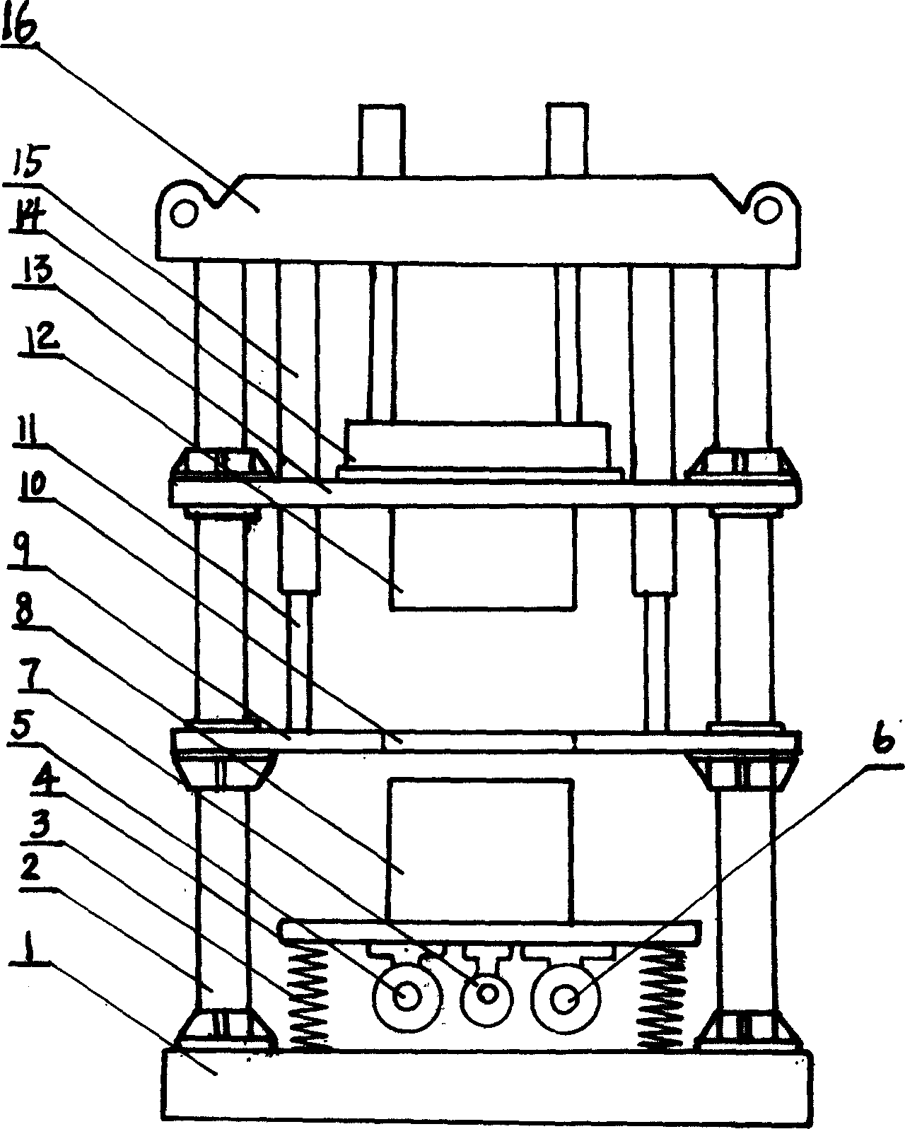
[0018] The frequency and amplitude modulation combined force forming machine described in Example 1 is composed of a hydraulic device, a forming device and a vibration device. The vibration device is composed of a high-frequency vibration excitation device and a frequency converter. The vibration device is fixed on the base (1). A column (2) is placed vertically on the four corners of (1). The upper ends of the columns (2) are respectively fixed on the four corners of the top beam (16). The hydraulic device is fixed on the top through the upper end of the movable mold table (13). The lower end of the beam is fixed on the demolding table (9). The forming device is composed of the movable die table (13), the demolding table (9), the mold frame (24) and the mold. The high-frequency excitation device is mounted on two sets of shafts. It is composed of motors with eccentric wheels, each group has two motors, and the rotation speed is the same and the direction is opposite. The mass of the eccentric wheels (22) is correspondingly equal, and a gear synchronizer (20) is connected between a group of two shafts. , The frequency converter is composed of a motor (7) and more than one eccentric wheel (22), the speed of the motor (7) on the frequency converter is greater than the speed of the motor (5) and the motor (6) of the high frequency vibration device, the frequency converter Connected with a transformer, the frequency converter can be stepped and steplessly frequency converted, and the frequency converter can be installed in different directions on the bottom surface of the vibration table (4).

Example Embodiment

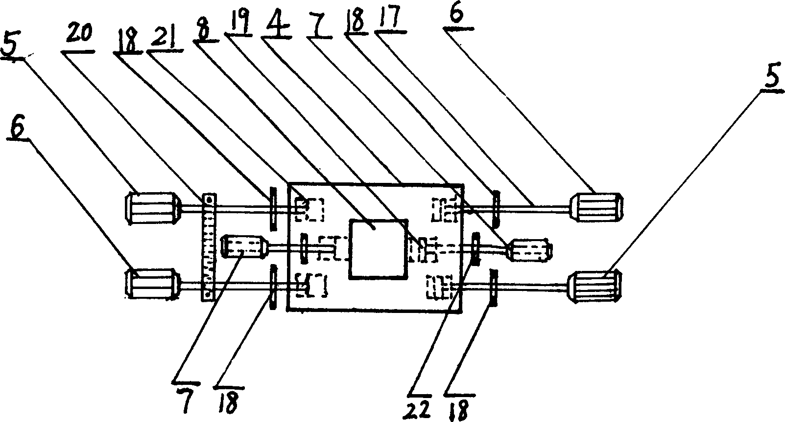
[0019] The guiding vibration column (8) of the frequency and amplitude modulation combined force forming machine described in embodiment 2 is in the shape of a box, and the box is divided into upper and lower layers. The high-frequency excitation device and the frequency converter are installed on the upper layer, and the lower layer is equipped with more than three The lower end of the spring and the vibration guide column (8) is directly connected with the base (1).

Example Embodiment

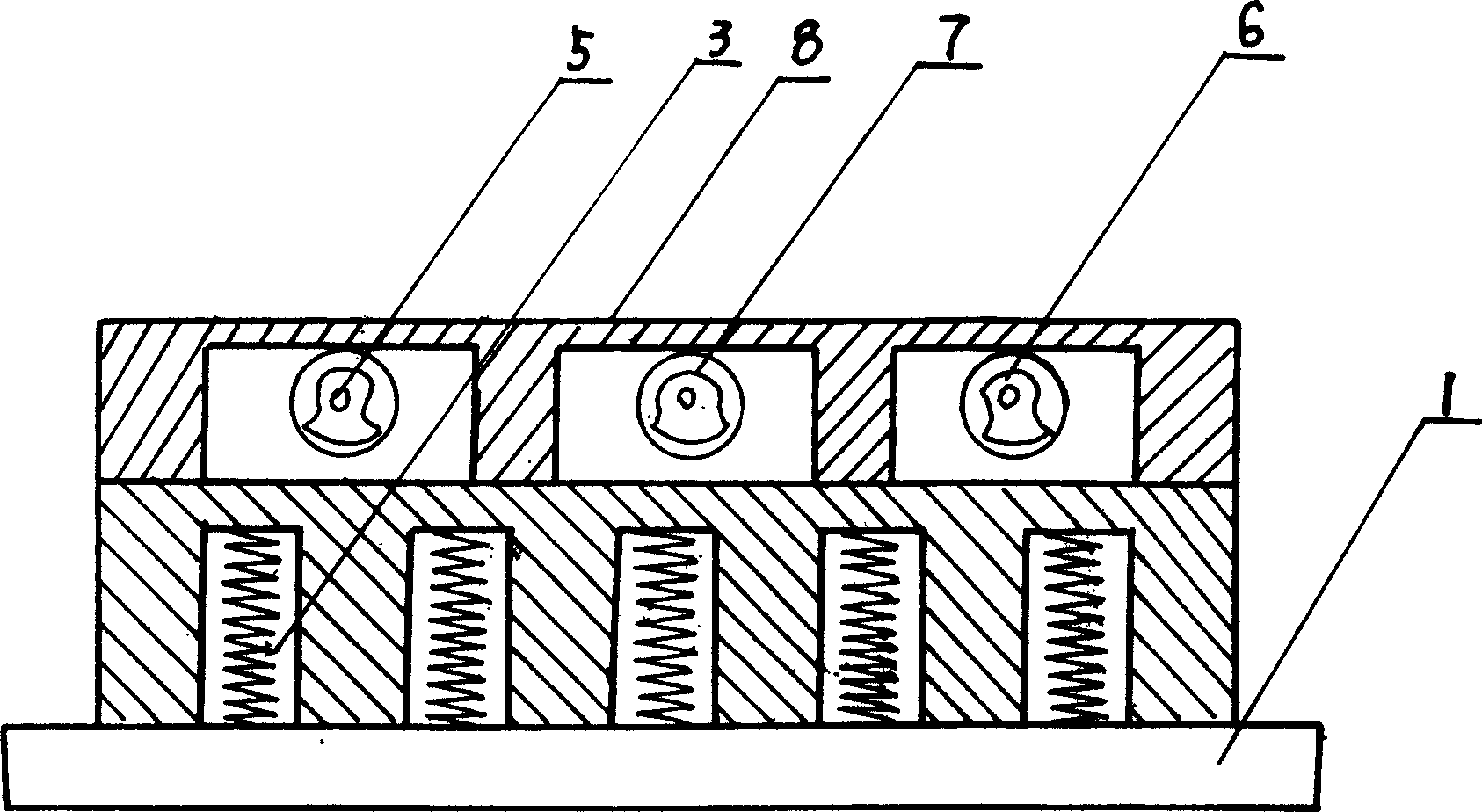
[0020] The side view of the vibrating table (4) of the frequency and amplitude modulation combined force forming machine described in embodiment 3 is dumbbell-shaped, and the high-frequency excitation device and the frequency converter are respectively installed in the cavities on both sides. The connection between the two cavities The bottom surface is on the upper surface of each cavity, the upper surface of the connecting surface can be placed on the mold frame (24), the lower surface is connected with more than three springs, the lower surface of the cavity and the lower end of the spring are both connected to the base (1) The upper surface is connected.
[0021] The implementation of the present invention has the following advantages:
[0022] The frequency and amplitude modulation combined force forming machine provided by the present invention is composed of a hydraulic device and a vibration device. The vibration device is composed of a high-frequency vibration excitation device and a frequency converter. The vibration excitation device and the frequency converter can be sealed and applied to dry powder In more occasions, its structure is simple, beautiful in appearance, easy to operate, safe and fast in molding speed, which completely solves the problem of spallation of fine powder and micro powder products, and its vibration amplitude and frequency are changed from the single form of the past to nothing. Level frequency modulation, by simply vibrating up and down, and then increasing the appropriate lateral vibration force, just like artificial sieving, it will make the product more compact.

PUM

no PUM

Description & Claims & Application Information

We can also present the details of the Description, Claims and Application information to help users get a comprehensive understanding of the technical details of the patent, such as background art, summary of invention, brief description of drawings, description of embodiments, and other original content. On the other hand, users can also determine the specific scope of protection of the technology through the list of claims; as well as understand the changes in the life cycle of the technology with the presentation of the patent timeline. Login to view more.
Why Eureka
Try Eureka