Heat measuring apparatus and method thereof

A technology of thermal testing and control devices, applied in the direction of measuring devices, calorimeters, measuring heat, etc., can solve problems such as test verification cannot be carried out, air flow loss in air ducts, single test points, etc., to achieve comprehensive test items and reduce measurement errors , the effect of high measurement accuracy

Inactive Publication Date: 2004-01-28
HUAWEI TECH CO LTD
View PDF0 Cites 21 Cited by
  • Summary
  • Abstract
  • Description
  • Claims
  • Application Information

AI Technical Summary

Problems solved by technology

However, these types of anemometers cannot well satisfy the internal flow field simulation and distribution testing of electronic communication equipment.
The reason is that electronic communication equipment mostly adopts the form of front-mounted plug-in panels, such as figure 1 As shown, the single-board panels of each printed circuit board are vertically inserted into the machine slot facing forward, so if the existing tester is used, the single-board panels must be removed, but the removal of the single-board panels will cause the air volume in the air duct to decrease. However, the processing and testing process holes on the panel not only need to be processed ...

Method used


Image

  • Heat measuring apparatus and method thereof
  • Heat measuring apparatus and method thereof
  • Heat measuring apparatus and method thereof

Examples


Embodiment Construction

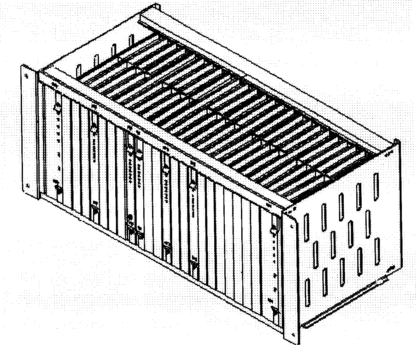
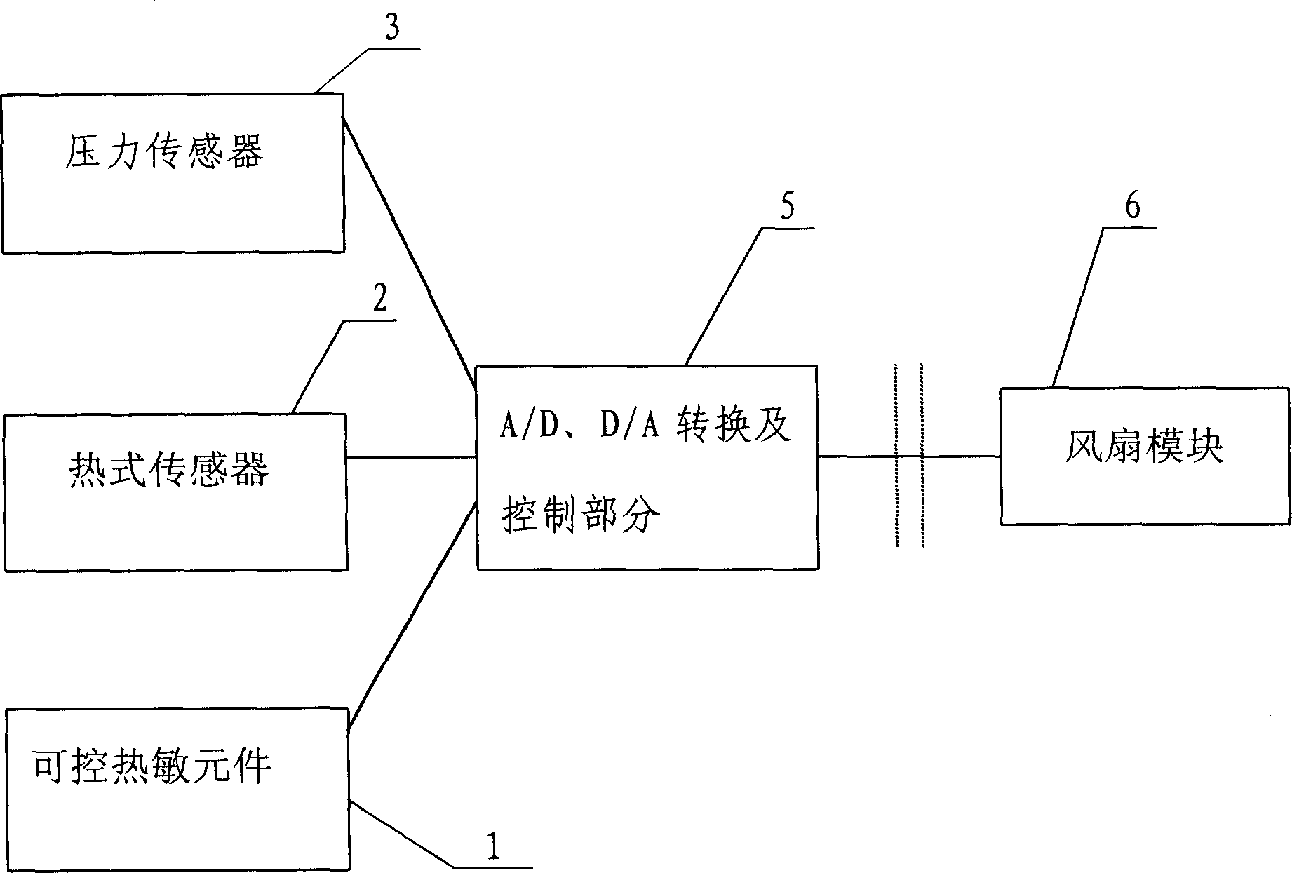
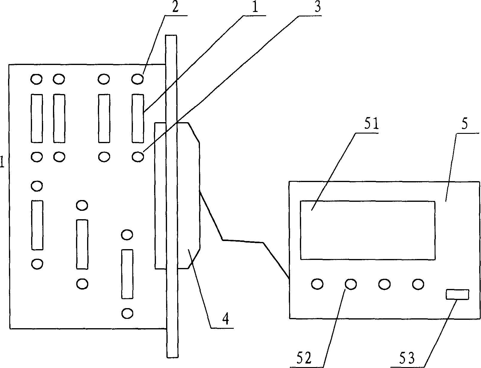
[0029] Such as Figure 1-Figure 3 Shown, thermal testing device described in the present invention comprises:

[0030] A controllable thermal element 1 used to simulate the heat source generated by the heating element;

[0031] Thermal sensor 2 for detecting temperature and wind speed signals;

[0032] A differential pressure sensor 3 for collecting pressure signals;

[0033] A multi-channel A / D, D / A conversion and control device 5 for converting multiple sets of temperature signals and pressure signals and controlling the controllable thermal element 1 and fan module 6;

[0034] A fan module that provides an air source for the analog board;

[0035] Among them, the layout of the controllable thermal element 1 analog communication equipment typical circuit board is installed on the analog single board 7, the thermal sensor 2 and the differential pressure sensor 3 are arranged on the analog single board 7 by plugging, and the thermal sensor 2 and the differential pressure s...


PUM


Abstract

The testing device comprises the controllable thermal sensor, hot type sensor, differential pressure sensor, multichannel A/D,Dú»A converters and control set, fan module. Configuration of typical circuit board of analog communication device for the controllable thermal sensor is installed on the analog single board. The hot type sensor and differential pressure sensor through socket joint mode are installed on the single board. The tested signals of the hot type sensor and differential pressure sensor and the control signal of the controllable thermal sensor through the linker on the analog single board and multichannel Aú»D,Dú»A converters are connected to the control device. Since no uniformity of wind speed on surface of PCB is tested at multiple test points in the invention, measuringerror of hand held devices is reduced. Thus, the invention can simulates heat dispersion status and test and validate fortified heat dispersion effect directly.

Description

technical field [0001] The invention relates to a thermal testing device and a testing method thereof, in particular to a thermal testing device and a testing method thereof for simulating the internal flow of air-cooled electronic communication equipment. Background technique [0002] With the increase of power consumption of electronic communication equipment and the decrease of structural volume, heat dissipation has become an important issue in product design. Thermal testing has become an important part of product design verification. However, in the prototype stage, sometimes due to imperfect product functions, the power consumption of the equipment cannot reach the maximum level, and the heat dissipation index cannot be tested and verified in time. After the product development is completed, the test and verification often requires replacing the fan or changing the structure. It will cause problems such as increased noise and delay the product development cycle. [0...

Claims


Application Information

Patent Timeline
IPC IPC(8): G01K17/06G01N25/20
Inventor 马金东刘标奇
Owner HUAWEI TECH CO LTD
Why Eureka
Try Eureka