Chemical machinery grinding equipment

A technology of chemical machinery and equipment, applied in the field of chemical mechanical grinding equipment, can solve the problems of poor production line management efficiency, inability to further reduce size, increase production capacity, etc.

Inactive Publication Date: 2004-01-28
UNITED MICROELECTRONICS CORP
View PDF0 Cites 12 Cited by
  • Summary
  • Abstract
  • Description
  • Claims
  • Application Information

AI Technical Summary

Problems solved by technology

[0005] by the above figure 1 In the setup, it can be clearly seen that the size of the circular lapping platen must be larger than the wafer because other units, such as regulators and/or slurry supply lines are mounted on or above the platen; In other words, the size of CMP equipment is limited by the size of the platen, which must be larger than the size of the wafer. When the size of the wafer continues to increase, the design of traditional CMP equipment cannot further reduce the...

Method used


Image

  • Chemical machinery grinding equipment
  • Chemical machinery grinding equipment
  • Chemical machinery grinding equipment

Examples


Embodiment Construction

[0031] In order to make the above and other objects, features, and advantages of the present invention more comprehensible, a preferred embodiment will be described in detail below together with the accompanying drawings.

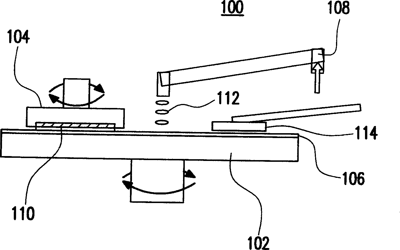
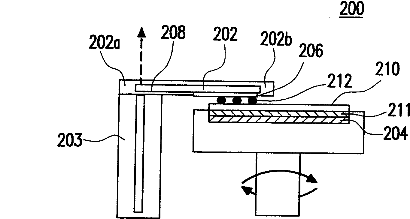
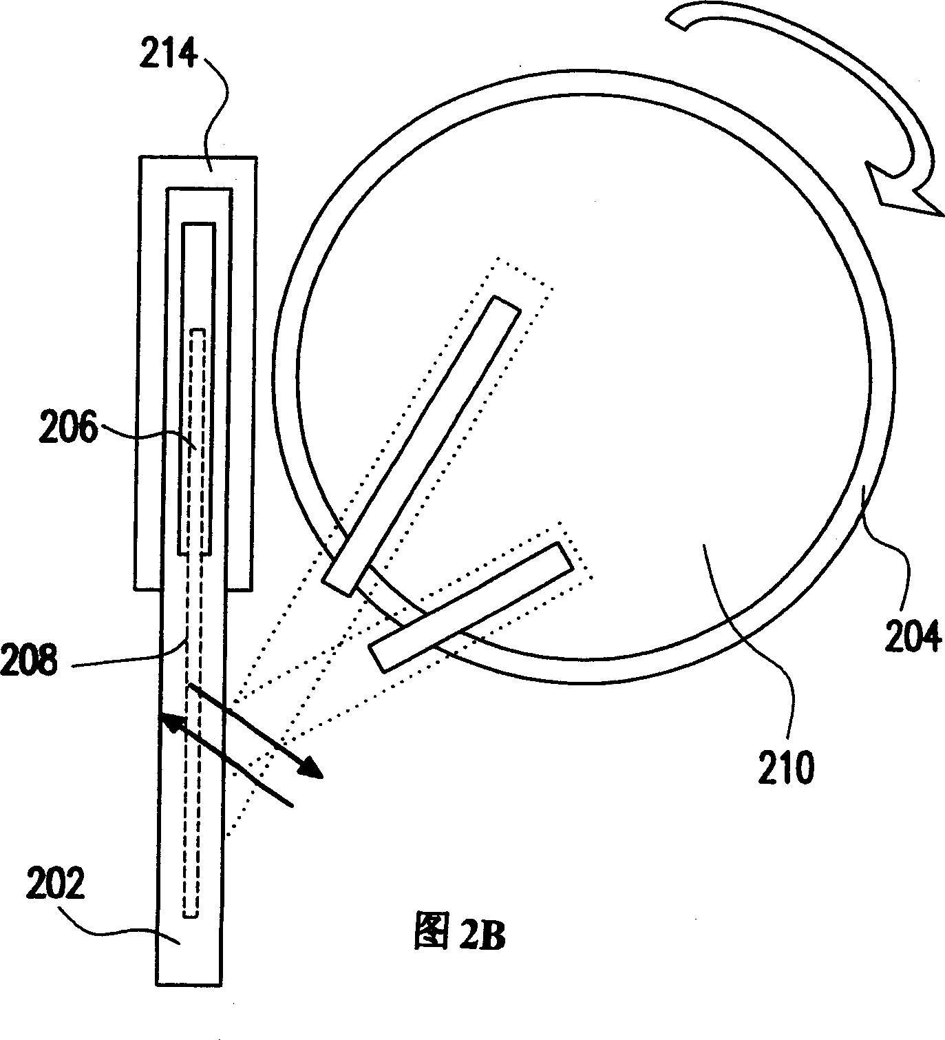
[0032] The design of the present invention can reduce the size of the CMP equipment by using a slender press plate, which is used as a grinding press plate, and the principle of the design is to make it into a slender shape or a rectangle. Please refer to Figure 2A 2B introduces a sectional view and a top view of a CMP device according to a preferred embodiment of the present invention. The core unit of the CMP device 200 includes an elongated grinding platen 202 and an automatically rotating wafer handle 204. The elongated grinding platen 202 is preferably elongated, and one end 202a of the grinding platen 202 is preferably fixed at a position around the wafer handle 204, and the elongated platen 202 can revolve around a rotation axis Z at the fixed end 2...


PUM


Abstract

The invented chemical mechanical polishing (CMP) device is suitable to present manufacturing technique. Slim grinding pressboard with size less than the size of wafer is utilized in the invented CMP device. Thus, the layout can be pressed and space can be used effectively so as to reach high yield and effective production management. The CMP device can select diversified grinding pad and/or grinding pulp, thus, flexible manufacturing procedure can be arranged by the CMP device.

Description

technical field [0001] The present invention relates to a chemical mechanical polishing apparatus, and more particularly to a chemical mechanical polishing apparatus having at least one elongated platen. Background technique [0002] As semiconductor components continue to shrink, the demand for multilayer interconnection increases relatively. The multilayer metal structure can provide greater flexibility in circuit design and actual reduction of chip size and chip cost. In integrated circuits, at least two to five metal layers are generally used, so it is important to perform a planarization step on the rough surface of the wafer, so that the fabrication process of multilayer interconnects can be carried out smoothly, and The wire pattern can be transferred more accurately. In addition, in the alignment system, the flattening of the wafer is the most important factor affecting the accuracy of the alignment. If the flattening step of the wafer is not done well, not only the...

Claims


Application Information

Patent Timeline
IPC IPC(8): B24B7/00B24B37/04H01L21/304H01L21/306
CPCB24B37/042B24B37/20
Inventor 胡绍中许嘉麟陈学忠许仕勋
Owner UNITED MICROELECTRONICS CORP
Why Eureka
Try Eureka