Photographing lens

A fiber amplifier and long-wavelength technology, applied in lasers, laser components, instruments, etc., can solve problems such as high noise figure, increased instantaneous gain change of long-wavelength fiber amplifiers, and low conversion efficiency

Inactive Publication Date: 2004-03-31
SAMSUNG ELECTRONICS CO LTD
View PDF0 Cites 7 Cited by
  • Summary
  • Abstract
  • Description
  • Claims
  • Application Information

AI Technical Summary

Problems solved by technology

Conventional gain control methods using optical components are known, but these methods have problems in that the configuration of the erbium-doped fiber amplifier is complicated, and it is also difficult to adjust its operating parameters depending on the position of the erbium-doped fiber amplifier
In addition, such a gain control device also has the problem that it is necessary to prevent the temporary overcurrent phenomenon of the output optical signal due to the increase or decrease of the number of channels
However, such a WDM optical communication network has problems in that the input / output optical power in a long wavelength band has low conversion efficiency due to low density conversion, and the noise figure is high
[0010] However, if figure 1 As shown, in the traditional long-wavelength fiber amplifier that uses the first pumping light at 980nm to cause the second amplification of the erbium-doped fiber, the second pumping operation causes a delay in the response speed, thereby causing a control time delay Δt1
This control delay results in an increase in the instantaneous gain change ΔP1 of the long-wavelength fiber amplifier
These instantaneous gain changes ΔP1 will accumulate during long-distance optical transmission, resulting in errors in the optical signal

Method used


Image

  • Photographing lens
  • Photographing lens
  • Photographing lens

Examples


Embodiment Construction

[0020] The preferred embodiments of the present invention will be described in detail with reference to the drawings. In the following description, when the subject of the present invention may be made more unclear, detailed descriptions of known functions and configurations included herein will be omitted.

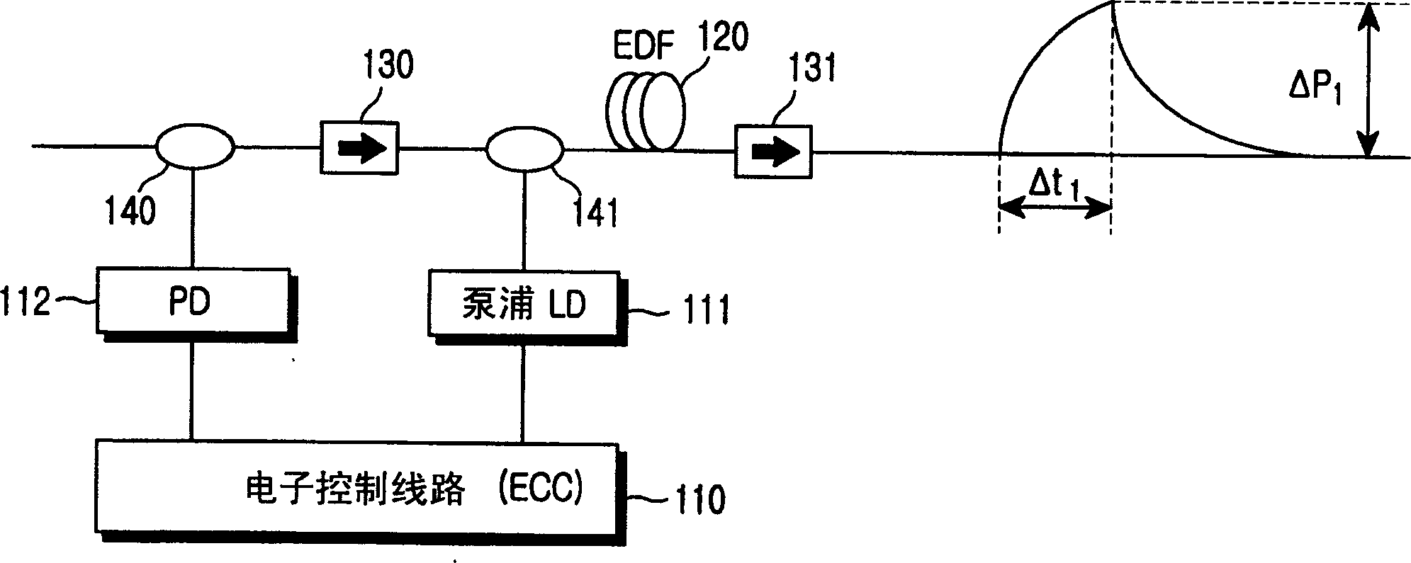
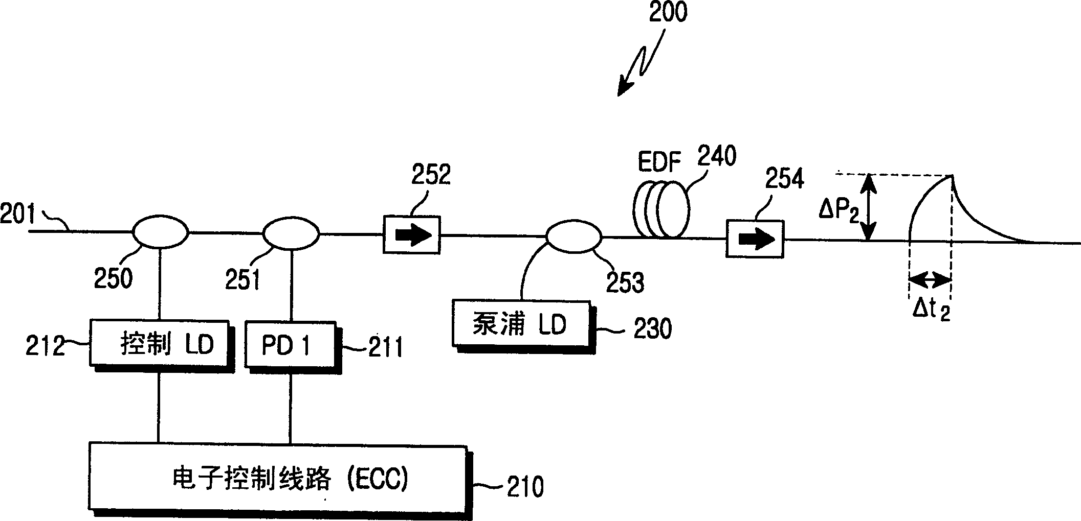
[0021] reference figure 2 According to the first embodiment, the long-wavelength fiber amplifier 200 for amplifying the long-wavelength input optical signal 201 includes: a first pump light source 230, a photodetector 210, first and second wavelength selective couplers 250 and 253, A beam splitter 251, and first and second isolators 252 and 254. The first pump light source 230 generates and outputs the first pump light of 980 nm. The photodetector 211 detects the light intensity of the input optical signal 201. The controller 210 calculates the amount of light intensity loss of the input optical signal 201 and the number of channels, and provides an output control signal acc...


PUM

PropertyMeasurementUnit
wavelengthaaaaaaaaaa

Abstract

An optical fiber amplifier is disclosed for amplifying an input optical signal in the long wavelength band. The amplifier include first and second pumping light sources, a photo detector for detecting the intensity of the input optical signal, an erbium-doped optical fiber, and a controller. The optical fiber is brought to a first-pumped state by the first pumping light output from the first pumping light source. This generates an amplified spontaneous emission in the short wavelength band. The optical fiber is brought to a second-pumped state by the amplified spontaneous emission and outputs an induced emission light in the long wavelength band. The second pumping light source outputs a second pumping light in the same wavelength band as the amplified spontaneous emission, while controlling the intensity of the second pumping light by an output control signal, thereby controlling the intensity of the second-pumped state of the optical fiber. The controller calculates the amount of optical intensity loss and the number of channels of the input optical signal, based on the detected optical intensity, and transmits the output control signal to the second pumping light source for compensating the loss of the input optical signal.

Description

Technical field [0001] The present invention relates to an optical fiber amplifier, and more specifically, to a long-wavelength optical fiber amplifier including a long-wavelength band erbium-doped optical fiber. Background technique [0002] Problems related to noise systems and gain flattening appear in erbium-doped fiber amplifiers. This has caused an increase in the demand for gain control equipment. When there is a change in the number of input channels or the input light intensity, the equipment can automatically keep the gain of each channel consistent. Traditional gain control methods using optical components have been known, but the problem with these methods is that the configuration of the erbium-doped fiber amplifier is complicated, and it is difficult to adjust its operating parameters according to the position of the erbium-doped fiber amplifier. In order to solve these problems, another traditional method has been known, which adjusts the intensity of the pump ligh...

Claims


Application Information

Patent Timeline
Patent Type & Authority Applications(China)
IPC IPC(8): H01S3/06G02B6/00H01S3/0933H01S3/094H01S3/13
CPCH01S3/094023H01S3/1301H01S3/094003H01S3/094011H01S3/0677H01S3/10015H01S3/1608G02B6/00
Inventor 黄星泽辛烘硕姜秉昌
Owner SAMSUNG ELECTRONICS CO LTD
Why Eureka
Try Eureka