
Optical disk machine and its Servo control system and optical path modification servo control system

A servo control system and servo control technology, applied in the field of optical path correction servo control system, can solve the problems of inability to effectively control the timely compensation of the skateboard motor, and the inability to notify the skateboard motor servo control unit of the offset of the optical lens.

Inactive Publication Date: 2004-03-31
MEDIATEK INC
View PDF0 Cites 1 Cited by
  • Summary
  • Abstract
  • Description
  • Claims
  • Application Information

AI Technical Summary

Problems solved by technology

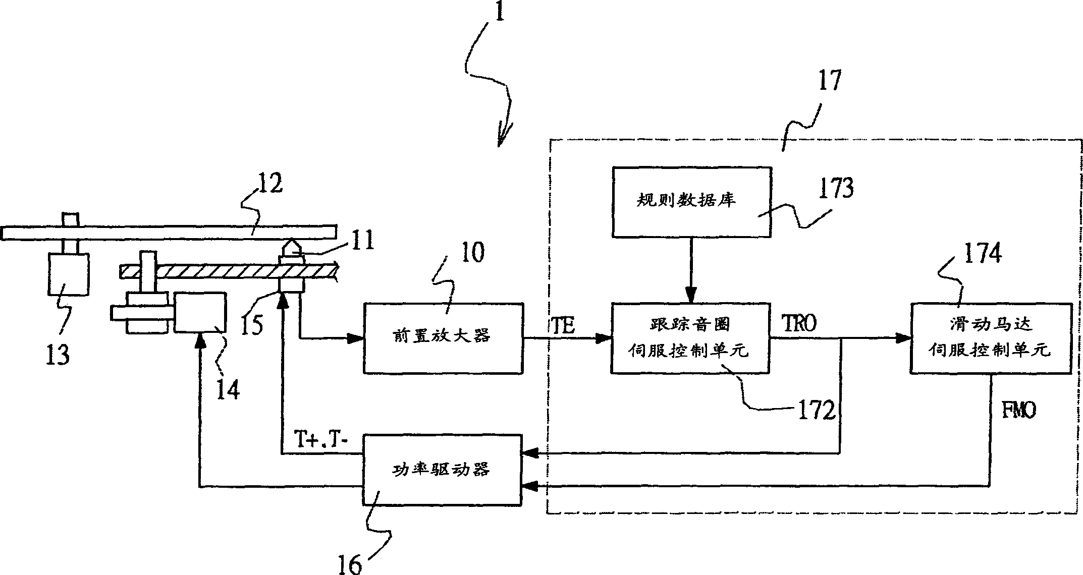
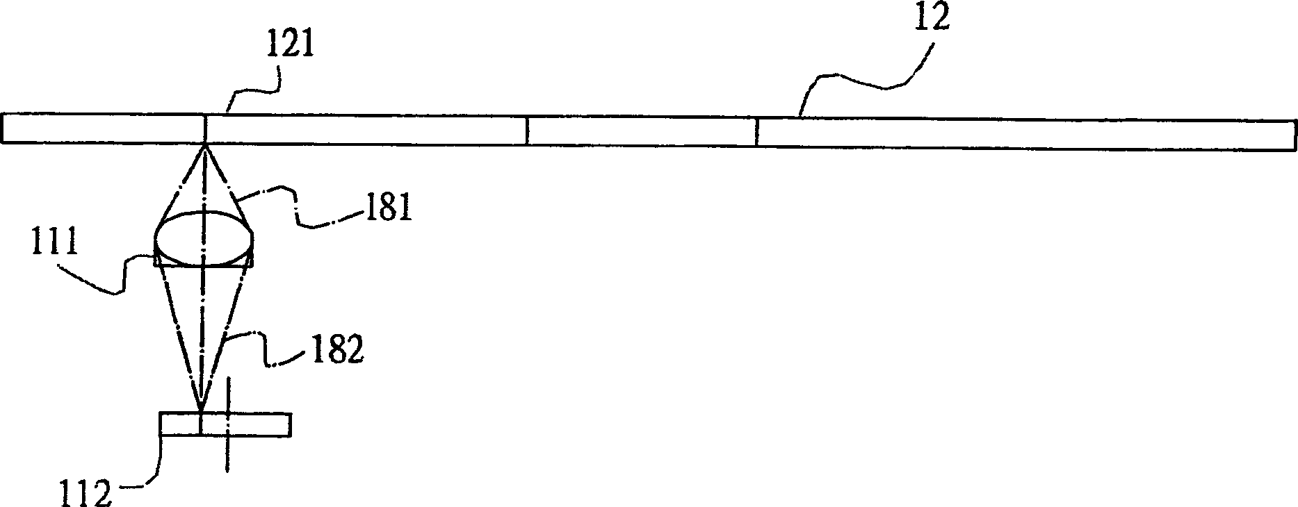
[0007] The reason why the aforementioned offset cannot be effectively compensated is that the offset of the optical lens 111 at the center of the optical path cannot be notified to the slider motor servo control unit 172, so that it cannot effectively control the slider motor 14 for timely compensation

Method used


Image

  • Optical disk machine and its Servo control system and optical path modification servo control system
  • Optical disk machine and its Servo control system and optical path modification servo control system
  • Optical disk machine and its Servo control system and optical path modification servo control system

Examples


Embodiment Construction

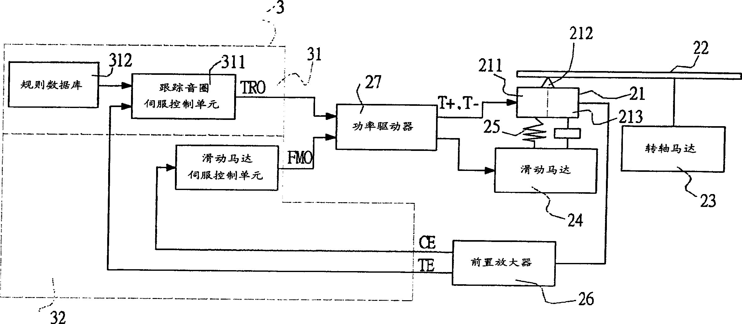
[0016] Please refer to image 3 , image 3 is the structure of the optical disc player 2 according to the preferred embodiment of the servo control system of the present invention. This optical disc drive 2 includes an optical head 21, a spindle motor 23 responsible for rotating the disc 22, a slide motor 24 for carrying the optical head 21 to move, a tracking coil motor 25 on the optical head 21, and a preamplifier 26 And a power driver 27 and a servo control system 3.

[0017] The optical head 21 includes a light source 211 for outputting light beams to the disc 22, an optical lens 212 (also known as an objective lens) for focusing the light beams, and an optical sensing unit 213. The light source 211 can be a laser light source, and the optical sensing unit The detection unit 213 is used to sense the reflected light beam from the disk 22 through the optical lens 212 and convert it into an electric signal correspondingly, and output it to the preamplifier 26 for amplificat...


PUM


Abstract

An optical path adjusting servo control system for use in an optical disc player which comprises an optical head and a slide plate motor for driving the optical head moving, characterized by that, the servo control system receives the central error signal representing the displacement corresponding the desired optical path location of the optical head to form a slide plate motor control signal for controlling the slide plate move. The system can adjust the optical head to a desired position and further accomplish the effect of eliminating light path.

Description

technical field [0001] The invention relates to an optical path correction servo control system for an optical disc drive, in particular to a servo control system for an optical disc drive and an optical path correction servo control system for an optical disc drive which can effectively eliminate optical lens offset and cause data read and write errors system and CD-ROM. Background technique [0002] Please refer to figure 1 , figure 1 The structure of a known optical disc drive is shown. This optical disc drive structure 1 includes an optical head (Pickup) 11, a spindle motor (SpindleMotor) 13 responsible for rotating the disc (Disc) 12, a slide plate motor (Sled Motor) 14 and optical head 11 for carrying the optical head 11 A tracking coil motor (Tracking Coil Motor) 15, a preamplifier 10, a power driver (Power Driver) 16 and a digital signal processing chip 17 on the top. The digital signal processing chip 17 has an optical path servo control function, and it include...

Claims


Application Information

Patent Timeline
Patent Type & Authority Applications(China)
IPC IPC(8): G11B7/09G11B7/095G11B21/10
Inventor 许汉文黄昭铭陈志远
Owner MEDIATEK INC
Learn More