

Surface acoustic wave filter and surface acoustic wave duplexer with the same
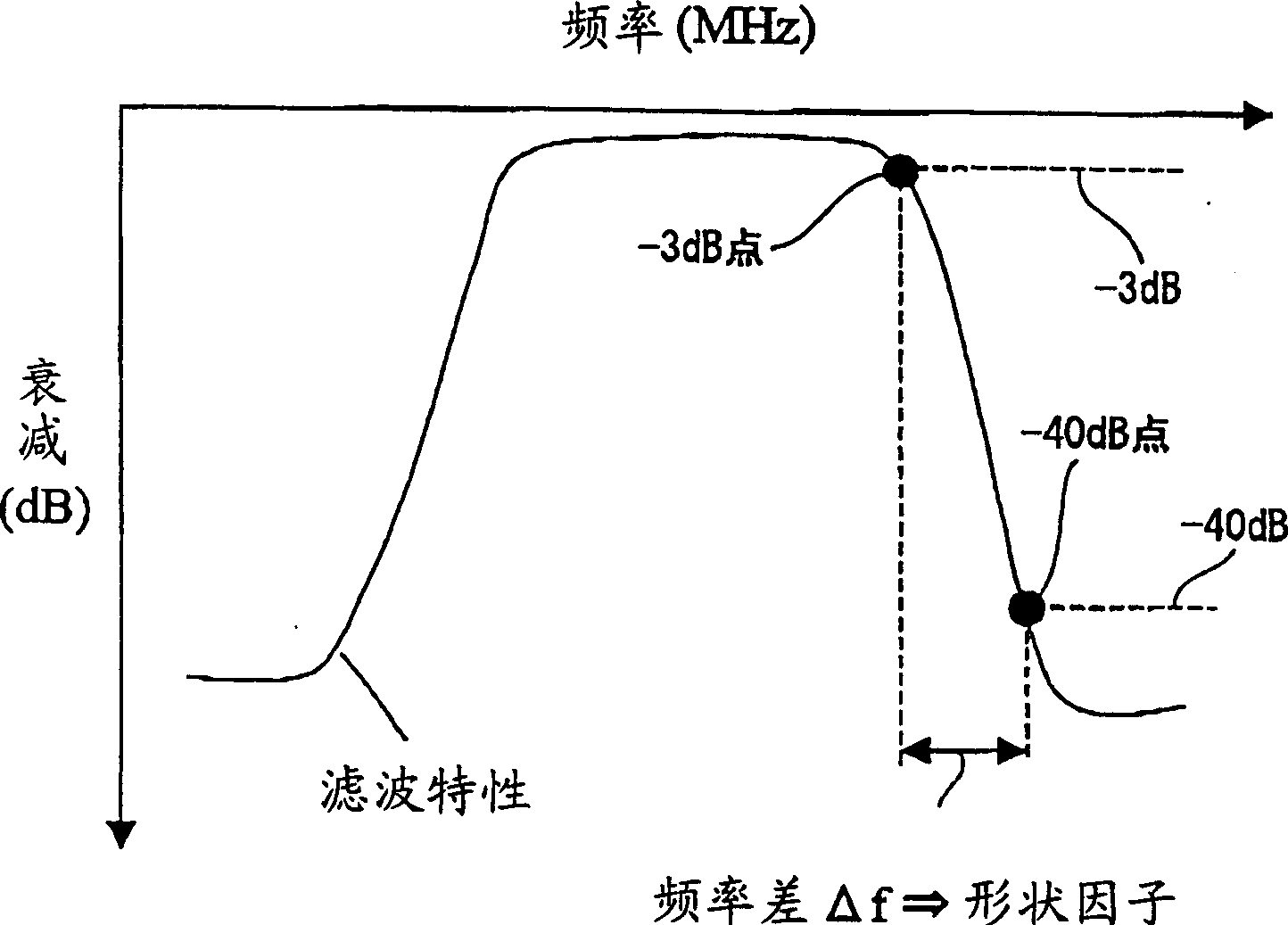
A surface acoustic wave and filter technology, applied in electrical components, impedance networks, etc., can solve problems such as poor band-pass characteristics of surface acoustic wave filters and form factors
- Summary
- Abstract
- Description
- Claims
- Application Information
AI Technical Summary
Problems solved by technology
Method used
Image

Examples
no. 1 example
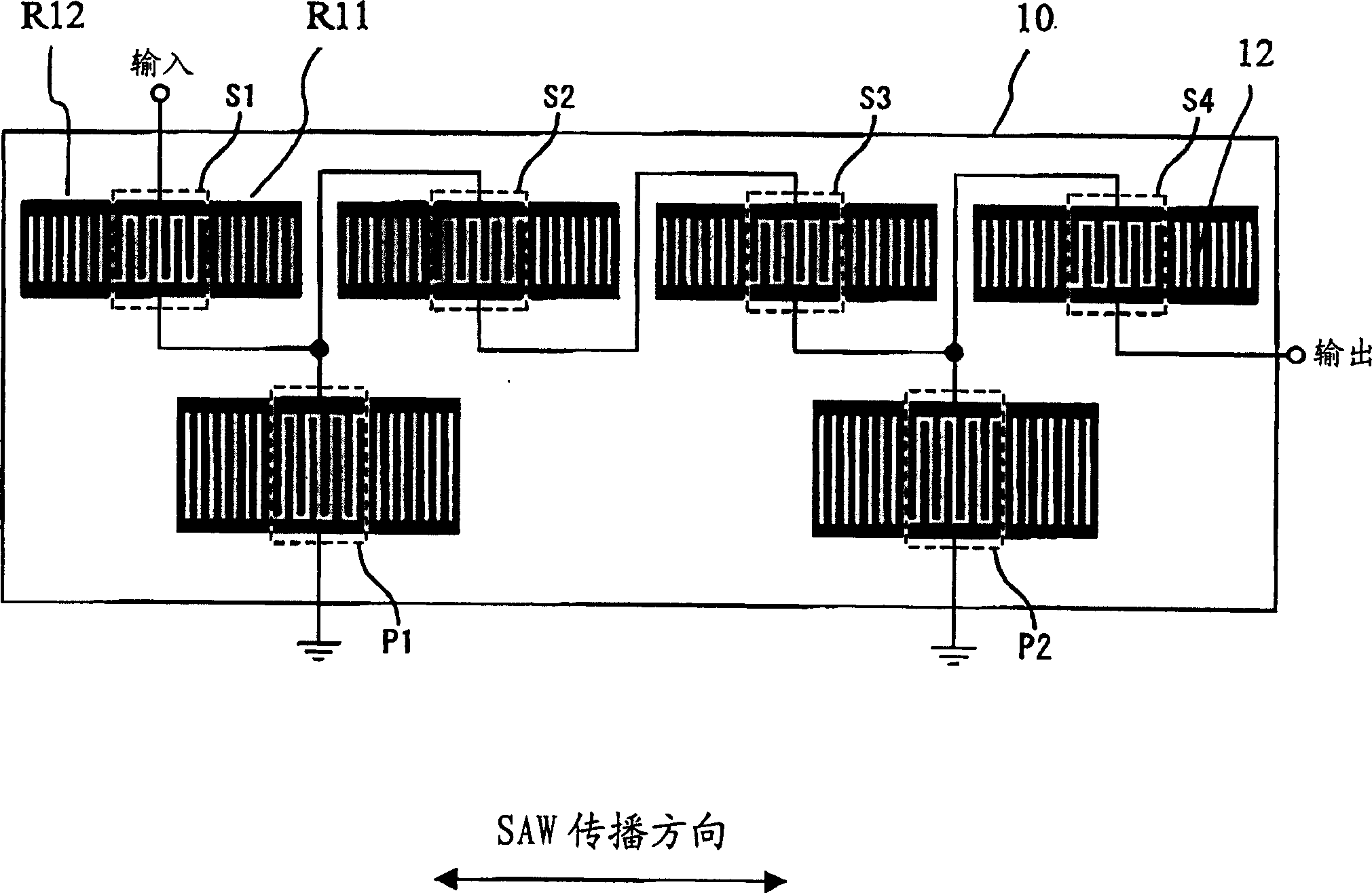
[0040] figure 2 is a plan view of a ladder-type surface acoustic wave (SAW) filter device 1 according to a first embodiment of the present invention. like figure 2As shown in , in a ladder structure, a ladder-type surface acoustic wave (SAW) filter device 1 includes four series branch resonators S1 to S4 arranged in series branches, and two parallel branches arranged in parallel branches way resonators P1 and P2.
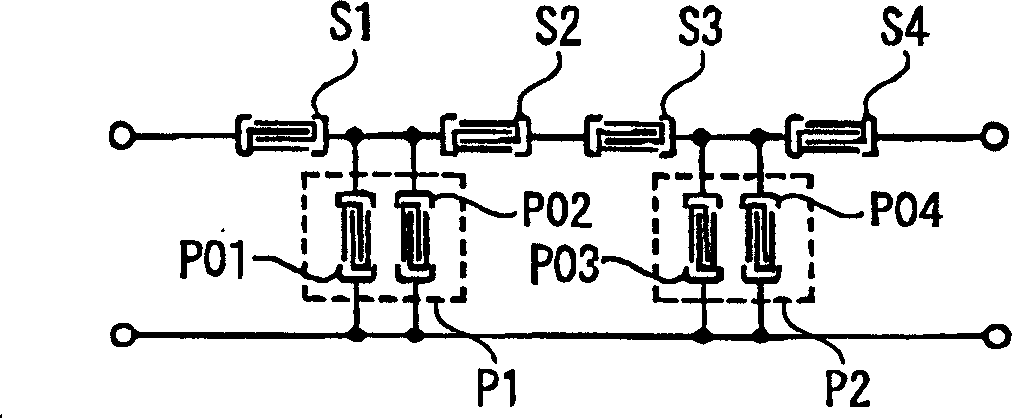
[0041] Here, the series branch resonators of the ladder-type SAW filter will be explained. figure 2 The ladder-type SAW filter device 1 shown in has a 4-level structure starting from the series branch resonator S1, and its circuit structure can be expressed as S-P-P-S-S-P-P-S, where each series branch resonator is represented by S, and each parallel resonator is represented by P express. image 3 A circuit diagram of the structure is shown. figure 2 The ladder-type SAW filter device 1 shown in 1 combines every two adjacent parallel branch resonators (P01 an...
no. 2 example
[0076] Refer below Figure 14 , a second embodiment of the present invention in the form of a ladder-type SAW filter device 2 is described in detail.
[0077] The structure and structure of the ladder type SAW filter device 2 of the present embodiment figure 2 The structure shown in is basically the same. Additionally, the piezoelectric substrate 10 is a 42° Y-cut X-propagation LiTaO 3 The substrate, which is the same as in the first embodiment.
[0078] In this structure, the electrode finger pitches of the series branch resonators S1, S2 and S4 are all 2.12 μm, and only the electrode finger pitch of the series branch resonator S3 is changed. If the static capacitance of the series branch resonator S1 is 1, then the relative static capacitances of the series branch resonators S2 to S4 are 1, 1 and 0.75, respectively. At the same time, the electrode finger pitches of the parallel branch resonators P1 and P2 are both 2.16 μm, and the relative static capacitance is 0.8.
...
no. 3 example
[0081] Refer below Figure 15 and 16 , to describe the third embodiment of the present invention in detail. In this embodiment, the ladder type SAW filter device 1 of the first embodiment is used as the relatively lower frequency side filter 1a, and the longitudinally coupled SAW resonator filter is used as the relatively higher frequency side filter 1b. These filters are installed in one package to form the 1.9GHz band antenna duplexer 1A. Figure 15 Such an antenna duplexer 1A according to the present embodiment is shown.
[0082] Figure 16 The filtering characteristics of this antenna duplexer 1A are shown in . from Figure 16 As can be clearly seen in , the high-frequency side form factor of the filter 1a on the low-frequency side is excellent. Therefore, although the frequency gap between the transmission band and the reception band is only 20 MHz, the attenuation rate of the antenna duplexer 1A of this embodiment is maintained at -40 dB or higher in the reception ...
PUM
 Abstract
Description
Claims
Application Information