Microbe detecting cell chip

A microbial detection and cell chip technology, applied in biological testing, microbial determination/inspection, biochemical equipment and methods, etc., can solve problems such as affecting detection accuracy, difficulty in large-scale detection, and damage to samples to be examined and biological probes

Inactive Publication Date: 2004-06-16
GONGIN PRECISION IND
View PDF0 Cites 6 Cited by
  • Summary
  • Abstract
  • Description
  • Claims
  • Application Information

AI Technical Summary

Problems solved by technology

[0007] In order to analyze a large number of detected cells or genes in parallel, many researchers have racked their brains to study how to effectively locate the specimen on the biochip. The most commonly used method is the micro-array technology, which is Use a robotic arm to fix the bioprobes on the biochip in a high-density array, and then use the extraction needle to contact the sample with the bioprobes for detection and analysis. However, in this method, each array point needs to be equipped with a bioprobe And the extraction needle, the components are too complicated, and the use of the extraction needle to absorb the object to be tested may easily cause damage to the object to be tested and the biological probe
[0008] Another way is to have a reaction zone with a fixed biological probe and a microchannel for injection and extraction of the sample solution. Although this configuration can effectively isolate the contact between the sample and the outside world, and achieve a good experimental control effect, it does not It will damage the sample, but due to cost and technical considerations, only a few reaction areas can be configured on a biochip, which is difficult to detect in large quantities, and multiple samples may be adsorbed by the probe in a single reaction area for subsequent follow-up. In fluorescence detection, since the activity and biological characteristics of each sample are different, it will affect the detection accuracy

Method used


Image

  • Microbe detecting cell chip
  • Microbe detecting cell chip
  • Microbe detecting cell chip

Examples


Embodiment Construction

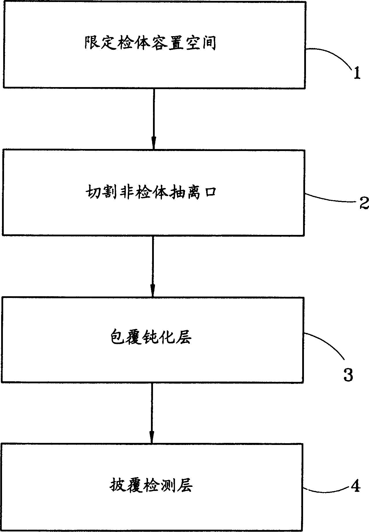
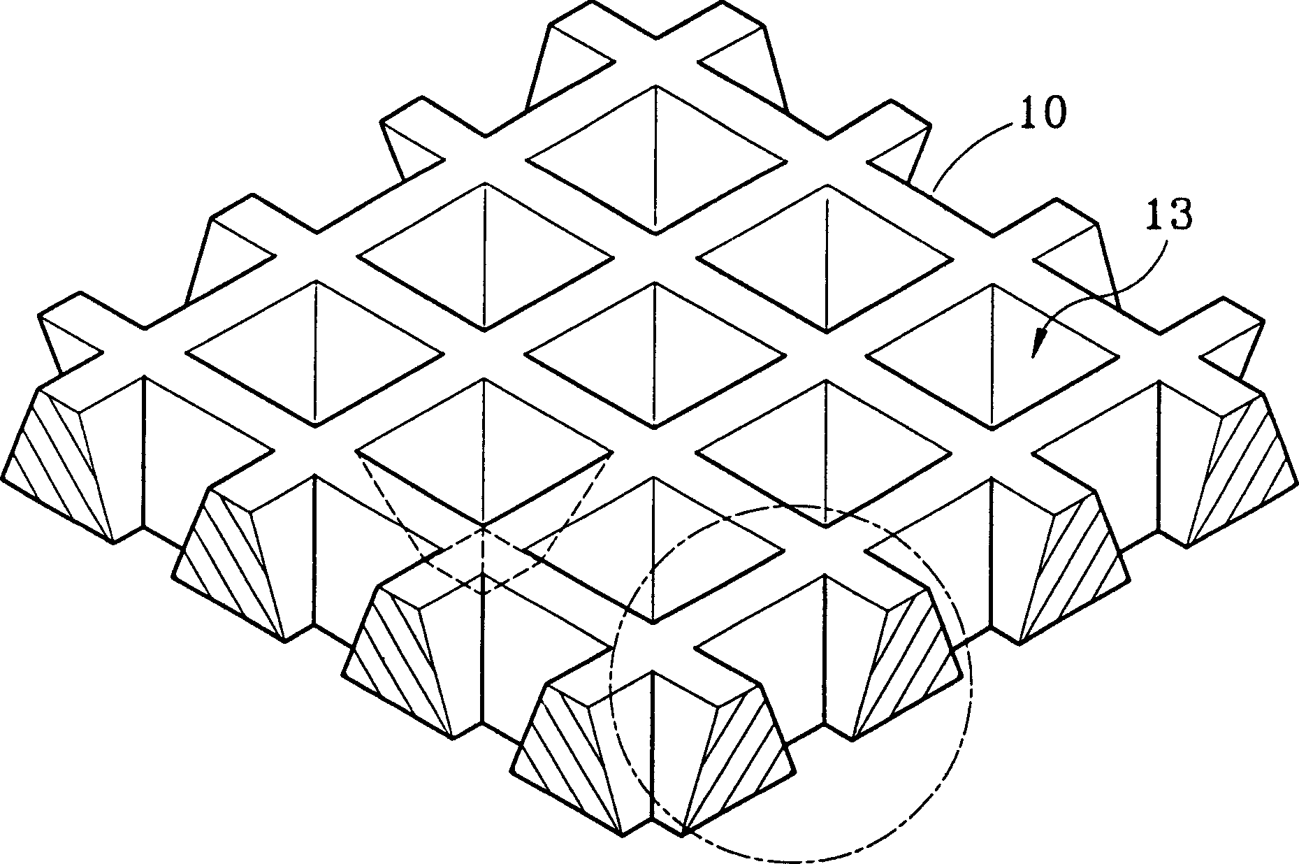
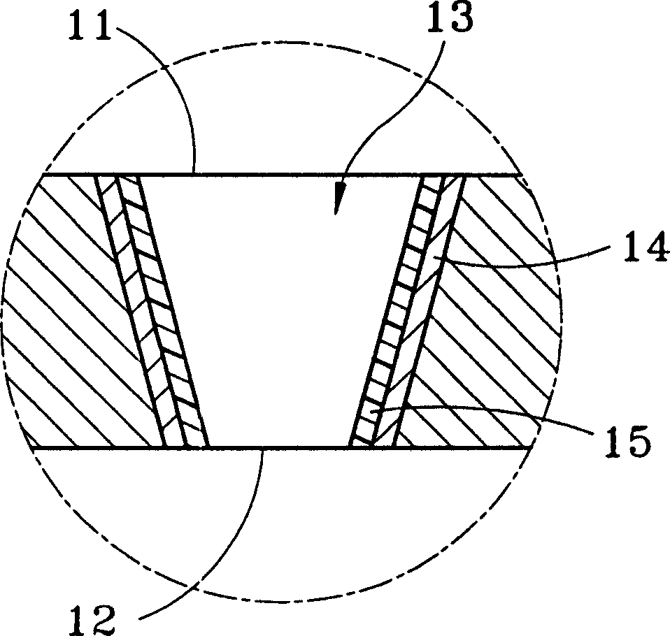
[0017] see figure 1 , 2-1 , 2-2 are schematic diagrams of the manufacturing process, three-dimensional appearance and partially enlarged cross-section of the present invention. As shown in the figure: the manufacturing method of the aforementioned biochip includes the following steps: defining the sample accommodating space 1, which is to cut the length and width of the silicon wafer on the chip with a length and a width of 2 cm each, in the manner of wafer etching and array arrangement ( 100 points in length and width, 10,000 points in total) defines a downwardly tapering sample indwelling space on the microbial detection chip 10, above which is a drop inlet 11, and the aforementioned etching technique can be wet etching or dry etching , Wet etching is performed by chemical reaction, while dry etching is performed by physical action.

[0018] After the specimen indwelling space is completed, the non-specimen withdrawal port 2 is cut, and the bottom of the indwelling space i...


PUM


Abstract

A microbiological detection cell chip comprises an accommodating area corresponding the size of the detected member, the upper portion of the accommodating area is provided by an instilling port for letting in the detected body fluid, the lower portion is provided with a drawing port for extracting the non-detecting member, a deactivation layer covered on the surface of the accommodating area for repairing and inactivating the accommodating area and providing the background for the optical detection, and a detection layer embedding the passive surface by biological compatible polymer, making each detected member accurately positioned in a single accommodating area for the subsequent detection.

Description

technical field [0001] The invention relates to a microbial detection cell chip, in particular to a biochip used to detect the location of a specific sample of a cell. Background technique [0002] Biochips are designed using the principles of molecular biology, genetic information, and analytical chemistry. They are high-tech components made of silicon chips, glass, or high-molecular organic plastics, combined with micro-electromechanical or other precision processing technologies. Rapid, accurate and low-cost bioanalytical testing capabilities. In advanced countries in Europe and the United States, chip functions are often used to speed up life science research and shorten the time for new drug development. [0003] The concept of biochips originated in the 1980s. According to their characteristics, biochips can be divided into gene chips, process chips (lab-on chips) and protein chips: [0004] 1. Gene chip (gene chip): It is a chip made by placing thousands to tens of ...

Claims


Application Information

Patent Timeline
Patent Type & Authority Applications(China)
IPC IPC(8): C12Q1/04G01N33/48
Inventor 苏友欣鲁希连刘大章龙训民黄荣山林世明刘得杏陈建勋李世光
Owner GONGIN PRECISION IND
Why Eureka
Try Eureka