

Grate
A technology of chain grate machine and hood, applied in the field of drive and tensioning device, can solve the problems of increased investment, consumption cost, increased hidden danger of accidents, attenuation of material strength, etc. Effect
- Summary
- Abstract
- Description
- Claims
- Application Information
AI Technical Summary
Problems solved by technology
Method used
Image

Examples
Embodiment Construction
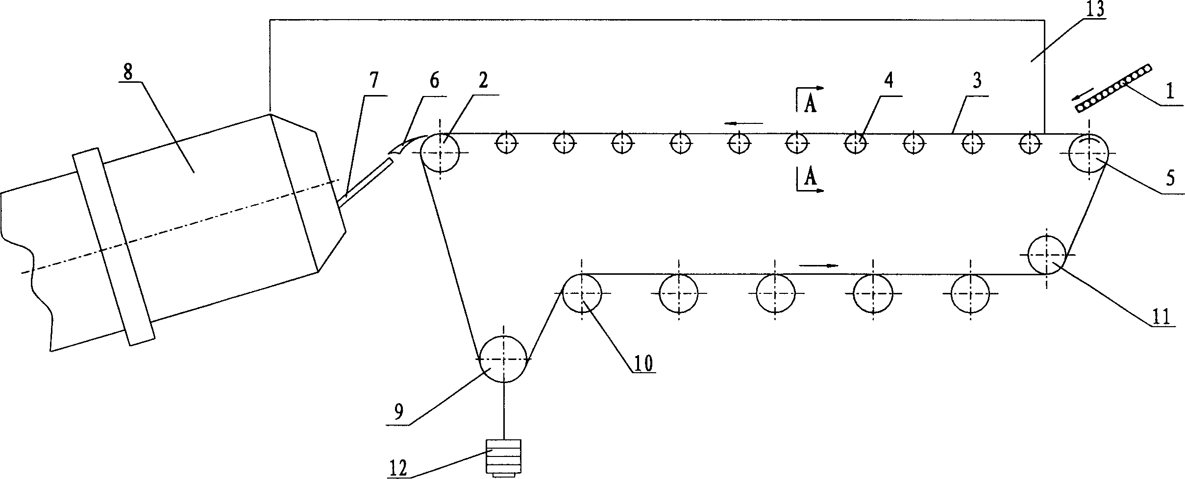
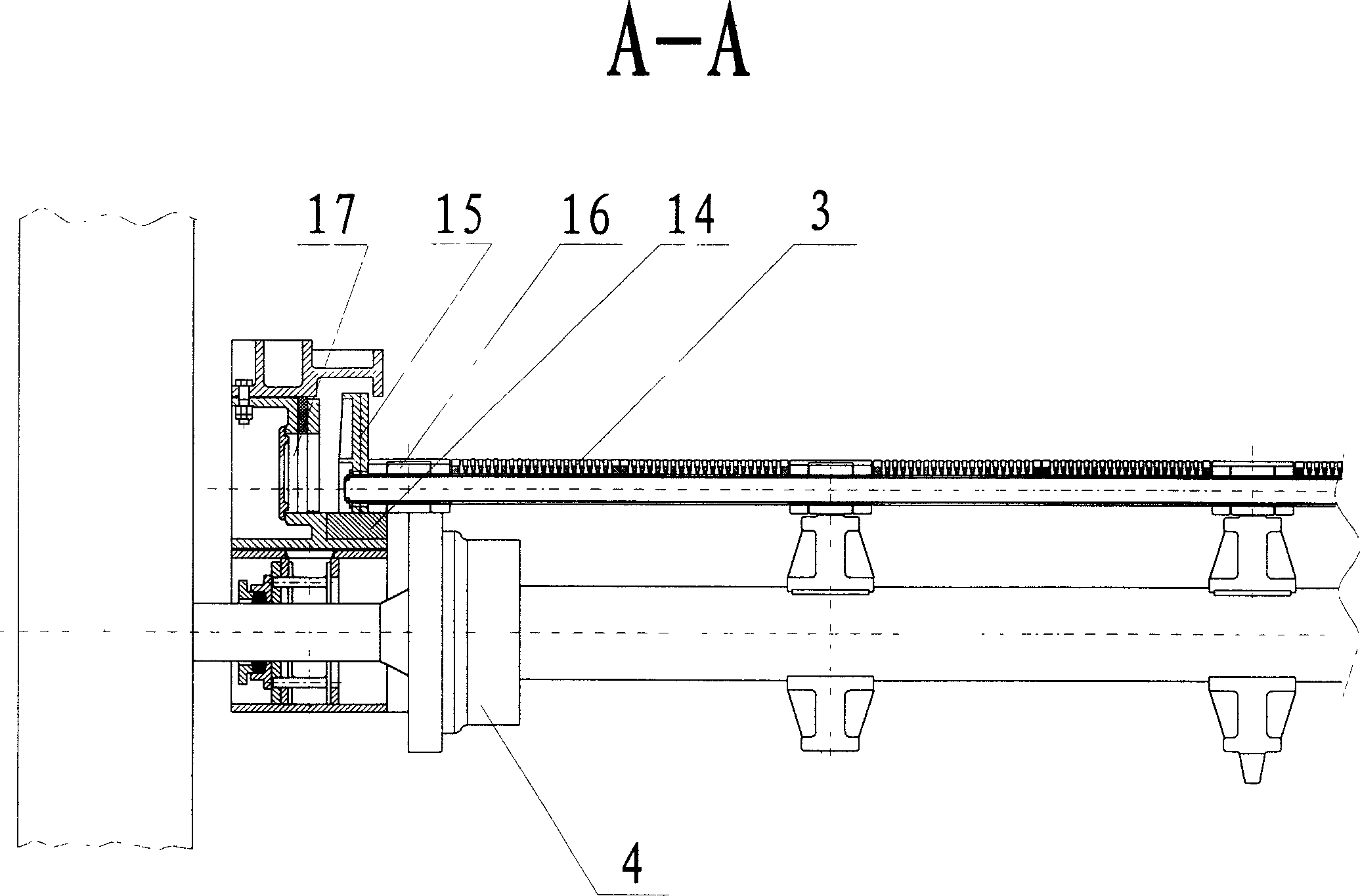
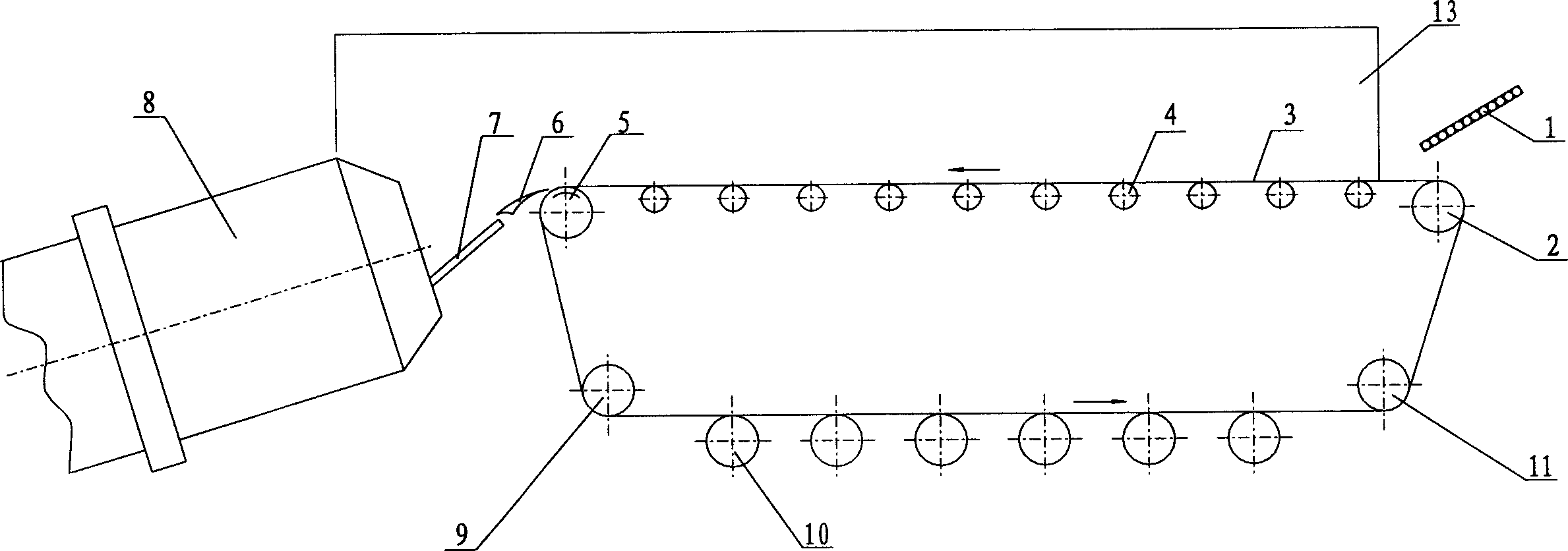
[0013] Such as figure 1 Layout, the driving head wheel 5 is set at the feeding end outside the machine cover 13, the tensioning wheel 9 is set at the lower end of the discharge tail wheel 2, vertical slideways (not shown) are installed on both sides of the bearing seat, and the weight is used to 12 counterweights are automatically tensioned. The upper loading operation grate bed 3 such as figure 2 Set up, use the chain link 16 of supporting wheel 4 to run the chain grate bed 3 and make the side plates 15 and the chain link 16 at the two ends of the running chain directly fall on the slide rail 14 of the side seal box 17. The chain grate bed 3 is kept horizontal by the horizontal shaft 18 supporting the load-carrying operation. The slide rail 14 is made of HS high-sulfur alloy steel. The discharge tail wheel 2 can be sprocket or light wheel, but the bed surface of the running chain grate bed 3 must form a complete arc surface at the tail wheel 2 to ensure that it is consist...
PUM
 Abstract
Description
Claims
Application Information