

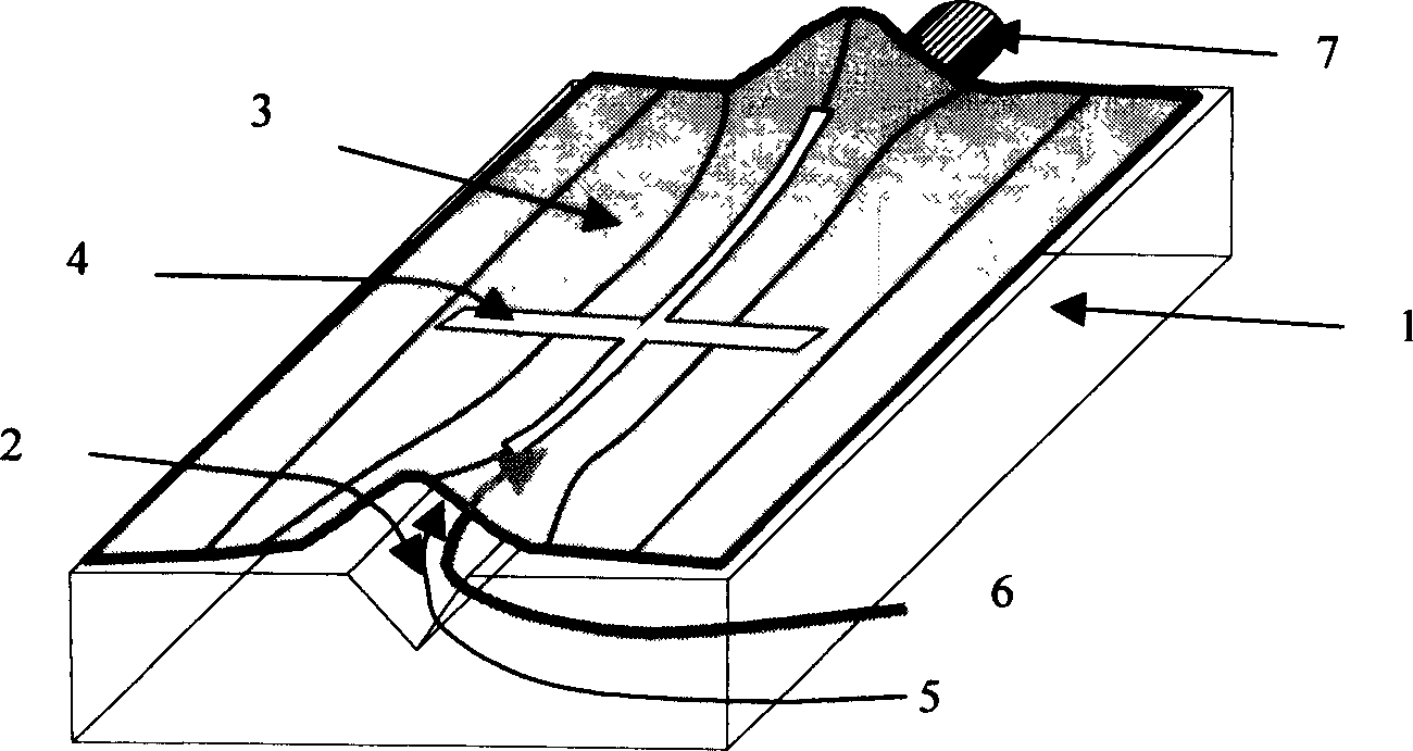
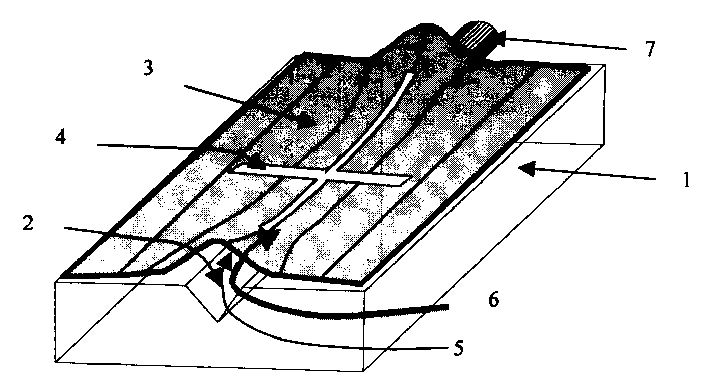
Adaptive microtype optical fibre connector
A fiber optic connector and self-adaptive technology, applied in the direction of optical waveguide light guide, optical waveguide coupling, etc., can solve the problems of damage, lack of space, and difficulty in grasping the scale of manual movement of micro-device structures, etc., and achieve the effect of small size
- Summary
- Abstract
- Description
- Claims
- Application Information
AI Technical Summary
Problems solved by technology
Method used
Image

Examples
Embodiment
[0024] Using single crystal silicon wafer as the substrate and electrodeposited nickel thin film as the cover material, a typical miniature optical fiber connector was prepared by multi-layer microstructure three-dimensional micromachining technology. The process is as follows:
[0025] Starting from thermally oxidized silicon wafers, first mask photolithography and then chemically etch with buffered hydrofluoric acid to open an etching window for the V-shaped groove 2, and then use 35% KOH to anisotropically etch at 70°C for about 3 hours to form V-groove 2. Fill the formed V-groove with photoresist (such as AZ4630, etc.), cure at low temperature, spin-cut and level off, spin-coat a 30-micron thick glue on the surface, go through photolithography, bake the glue at 90°C, and then spin-coat 5 microns The photoresist is then baked again at 95° C. for 100 minutes to form a semi-tapered photoresist structure that causes the two ends of the cover plate 3 to warp. Then photolithogra...
PUM
 Abstract
Description
Claims
Application Information