Liquid level stabilizing device in micro-analysis chip liquid pool and method of use thereof

A technology with stable liquid level and liquid storage tank, which is applied in the direction of microbial measurement/inspection, analytical materials, measuring devices, etc., to achieve stable liquid level, realize hydraulic pressure, and have a wide range of applications

Inactive Publication Date: 2004-08-25
ZHEJIANG UNIV
View PDF0 Cites 0 Cited by
  • Summary
  • Abstract
  • Description
  • Claims
  • Application Information

AI Technical Summary

Problems solved by technology

This method is suitable for keeping the liquid level in the liquid storage tank stable when there is a liquid f

Method used


Image

  • Liquid level stabilizing device in micro-analysis chip liquid pool and method of use thereof
  • Liquid level stabilizing device in micro-analysis chip liquid pool and method of use thereof
  • Liquid level stabilizing device in micro-analysis chip liquid pool and method of use thereof

Examples


Embodiment 1

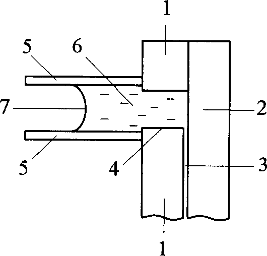
[0030] figure 1 . is a side sectional view of a preferred embodiment 1 according to the present invention. The microfluidic chip is composed of upper (1) and lower (2) two pieces. The upper (1) and lower (2) two pieces are sealed by bonding method, and the microchannel (3) is processed on the upper piece (1). . Holes are punched on the upper sheet (1) to form connecting channels (4). The chip is placed upright, and the horizontal channel (5) tube is directly fixed on the surface of the upper chip (1) around the opening of the connecting channel (4) to form a liquid storage pool. The liquid (6) in the liquid storage tank communicates with the microchannel (3), and the phase interface between the liquid (6) and the external atmosphere—the vertical liquid surface (7) is arc-shaped.

Embodiment 2

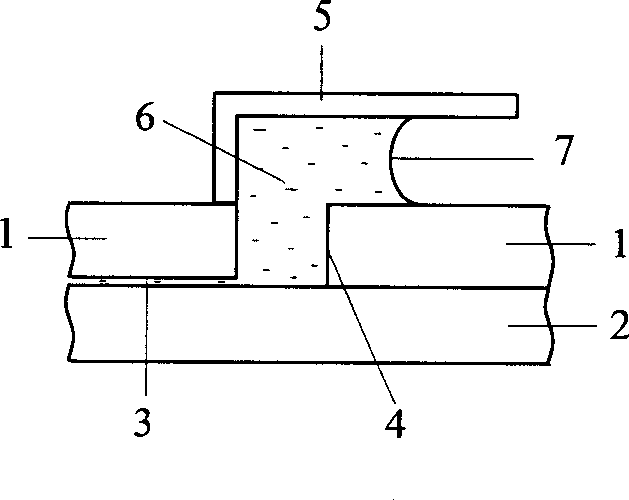
[0032] figure 2 . is a side sectional view of yet another preferred embodiment 2 of the present invention. The micro analysis and control chip is composed of upper (1) and lower (2). The bonding method is used to realize the sealing of the upper (1) and lower (2) pieces. Microchannels (3) are processed on the upper sheet (1). Holes are punched on the upper sheet (1) to form connecting channels (4). The chip is placed horizontally, and the horizontal channel (5) tube is directly fixed on the surface of the upper chip (1) around the opening of the connecting channel (4) to form a liquid storage pool. The liquid (6) in the liquid storage tank communicates with the microchannel (3), and the phase interface between the liquid (6) and the external atmosphere—the vertical liquid surface (7) is arc-shaped.

Embodiment 3

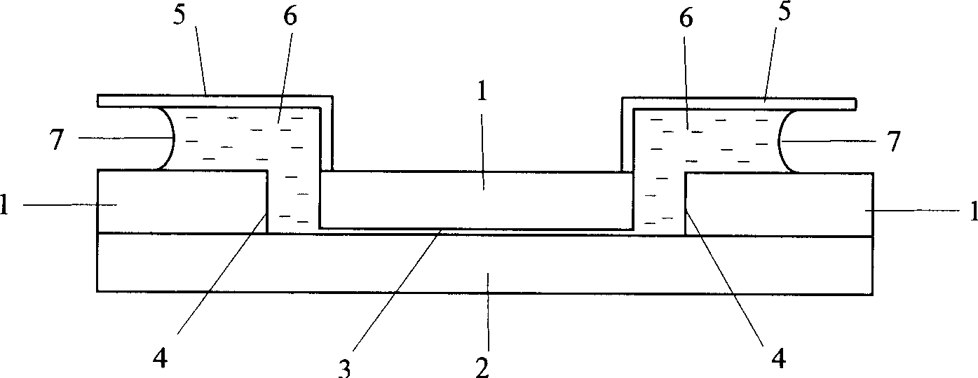
[0034] image 3. is a side cross-sectional view of a microfluidic chip for overall system liquid level stabilization according to a preferred embodiment of the present invention. The micro-analysis chip is composed of upper (1) and lower (2). The bonding method is used to realize the sealing of the upper (1) and lower (2) pieces. Microchannels (3) are processed on the upper sheet (1). A hole is punched at both ends of the microchannel (3) on the upper sheet (1) to form a connecting channel (4). The chip is placed horizontally, directly on the surface of the upper chip (1), and a horizontal channel (5) tube is fixed around the opening of the connecting channel (4) to form a liquid storage pool. The liquid (6) in the liquid storage tank communicates with the microchannel (3), and the phase interface between the liquid (6) and the external atmosphere—the vertical liquid surface (7) is arc-shaped. The two horizontal channels are on the same level.


PUM


Abstract

The invention relates to an integrated level stabilizing device used to liquor storing pond on microanalysis chip and using method. Its character: the liquor storing pond is composed of linking channel and horizontal inlet or outlet channel with level stabilizing function. Its advantages: during analysis, when liquor flows in or out of the liquor storing pond in effective control time, it can keep the level constant in the liquor storing pond, so as to avoid the interference to chip analysis course because of level change.

Description

technical field [0001] The invention relates to the field of microfluidic chip analysis, in particular to a liquid level stabilizing device in a liquid reservoir of a microanalysis chip and a method for using the same. Background technique [0002] Usually, the microanalysis chip is composed of upper and lower two or more layers of chips, and the material of the chip is single crystal silicon, or quartz, or glass, or high molecular polymer. The area of ​​the chip is about several square centimeters, and the width and depth of the microchannels are in the order of microns, which are generally closed microchannel networks. [0003] This patent relates to a liquid reservoir system on a microanalysis chip. Current on-chip reservoirs, literature (Manz A, Fettinger J C, Verpoorte E, Ludi H, Widmer H M, Harrison D J, Trend in Anal. Chem., 1991, 10:144) (Harrison D J, Manz A, Fan Z , Ludi H, Widmer H M, Anal.Chem., 1992,64:1926) (Jacobson S C, Hergen...

Claims


Application Information

Patent Timeline
IPC IPC(8): C12Q1/68G01N27/26G01N27/416G01N35/00
Inventor 方群李丹妮陈宏黄艳贞方肇伦
Owner ZHEJIANG UNIV
Why Eureka
Try Eureka