
Clock synchronizing semiconductor memory equipment

A storage device, semiconductor technology, applied in information storage, static memory, digital memory information, etc., can solve problems such as inability to achieve delay, impossibility of stable operation, and allowable reduction in efficiency

Inactive Publication Date: 2010-04-28
PS4 LUXCO SARL
View PDF5 Cites 0 Cited by
  • Summary
  • Abstract
  • Description
  • Claims
  • Application Information

AI Technical Summary

Problems solved by technology

In this case, the desired delay cannot be achieved, and a detection margin is caused to decrease, and stable operation is impossible
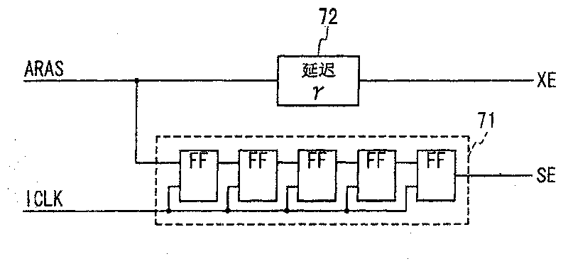
[0019] To overcome this problem, while allowing for reduced efficiency, it is necessary to set the time tRCDmin to seven clocks (23.1 ns) or the delay represented by an inverter chain that can generate the delay time independent of generating detection The period of the clock signal used by the circuit of the amplifier to activate the signal SE
However, it is difficult to achieve a stable inverter chain delay in all cases as it varies depending on processing conditions, temperature conditions and voltage conditions

Method used


Image

  • Clock synchronizing semiconductor memory equipment
  • Clock synchronizing semiconductor memory equipment
  • Clock synchronizing semiconductor memory equipment

Examples


Embodiment Construction

[0051] A clock synchronization type semiconductor memory device of the present invention is described below.

[0052] Figure 6 Denotes a bank circuit and a clock data storage section 31 provided as a common circuit section in the clock synchronization type semiconductor memory device according to the embodiment of the present invention. A clock synchronization type semiconductor memory device generally includes a plurality of banks, and a circuit for controlling the plurality of banks is commonly provided for the banks. Such examples are well known to those skilled in the art and will not be shown here. Although the clock data storage section 31 is provided for the common circuit section, it is assumed in this embodiment because the clock data storage circuit 31 is provided for each bank.

[0053] The clock data storage section 31 includes registers to store clock data representing the frequency of an external clock signal. In this example, clock data such as code 1 or cod...


PUM


Abstract

A synchronous type semiconductor memory device includes a memory cell array in which memory cells are arranged in a matrix; a row address decoder which activates one of word lines in said memory cellarray based on a row address in response to a word activation signal; a column decoder which activates one of bit line pairs in said memory cell array based on a column address; and a sense amplifiercircuit which amplifies a voltage difference on the activated bit line pair in response to a sense amplifier activation signal. The synchronous type semiconductor memory device further includes a clock data storage section which stores clock data showing a frequency or period of an external clock signal; and a control section which generates the word activation signal based on a row address strobesignal, and generates the sense amplifier activation signal based on the clock data and the row address strobe signal in response to an internal clock signal synchronous with the external clock signal.

Description

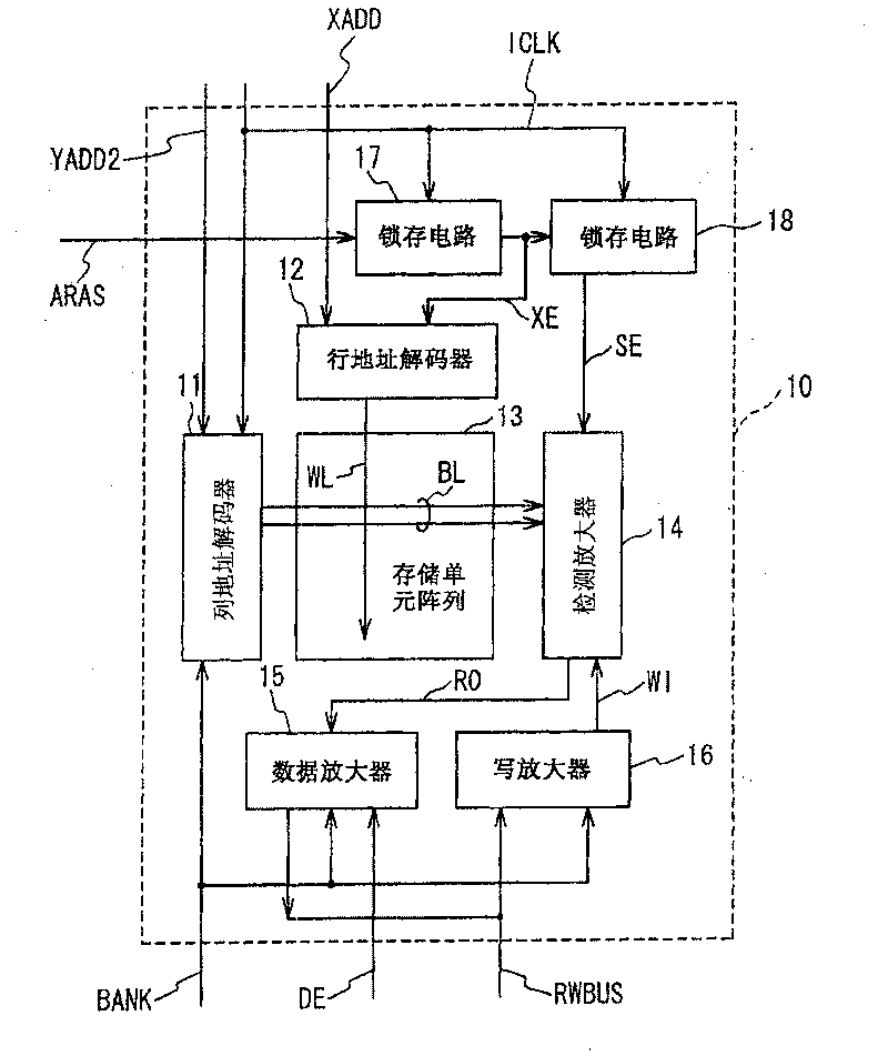
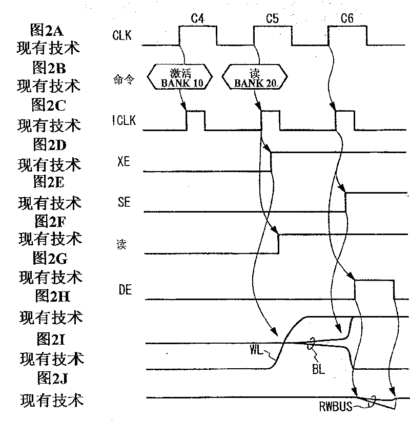
technical field [0001] The present invention relates to a semiconductor memory device that operates in synchronization with an external clock signal. Background technique [0002] A conventional clock synchronization type semiconductor memory device is described in Japanese Laid-Open Patent Application (KOKAI Publication No. Hei 8-129887). The structure and operation of a conventional clock type semiconductor memory device will be described below with reference to FIG. 1 . A conventional clock synchronization type semiconductor memory device operates in synchronization with an external clock signal, and has a plurality of memory blocks called banks. Each bank is determined based on a bank address. Control signals and address signals are supplied from external connection terminals in synchronization with an external clock signal. The internal clock signal ICLK is generated in synchronization with an external clock signal supplied from an external connection terminal, and i...

Claims


Application Information

Patent Timeline
Patent Type & Authority Patents(China)
IPC IPC(8): G11C11/34G11C7/22H03K5/00G11C7/10G11C11/407
CPCG11C7/1072G11C7/222G11C7/22G11C2207/2254
Inventor 江户幸子
Owner PS4 LUXCO SARL
Features
  • Generate Ideas
  • Intellectual Property
  • Life Sciences
  • Materials
  • Tech Scout
  • Unparalleled Data Quality
  • Higher Quality Content
  • 60% Fewer Hallucinations
Learn More