Central vortex column flash smelting process

A flash smelting and vortex technology, applied in crucible furnaces, electric furnaces, rotary drum furnaces, etc., can solve limited and other problems

Inactive Publication Date: 2004-09-15
CHINA NERIN ENG
View PDF0 Cites 12 Cited by
  • Summary
  • Abstract
  • Description
  • Claims
  • Application Information

AI Technical Summary

Problems solved by technology

As a countermeasure, it is effective to develop high-performance refractory

Method used


Image

  • Central vortex column flash smelting process
  • Central vortex column flash smelting process
  • Central vortex column flash smelting process

Examples


Embodiment Construction

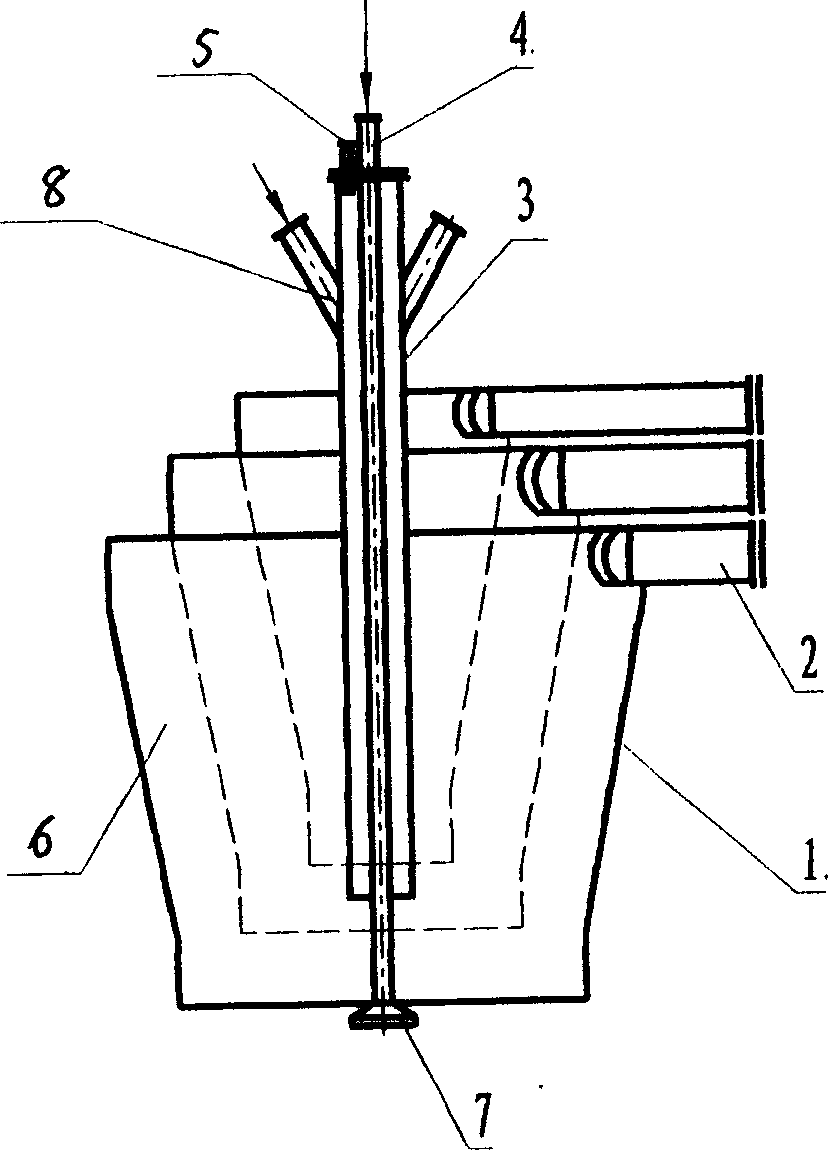
[0011] A central vortex column flash smelting process. The equipment of the process is composed of a reaction tower, a sedimentation tank and an ascending flue. The nozzle is the power source for generating the vortex column. The nozzle includes an air cavity 1 and an air inlet pipe 2; the air cavity 1 is Conical shape, the interior is vertically divided into a number of concentric vortex chambers 6 that are not connected to each other at the upper part and converge at the lower part. Each vortex chamber is equipped with 1-4 tangential air inlet pipes, and the concentrate slide pipe 3 penetrates The vortex chamber at the center of the air cavity is fixedly connected to the upper part of the vortex chamber. The atomizing air pipe 4 is fixed in the center of the concentrate chute 3 and passes through the concentrate chute 3. The lower end of the air pipe 4 is provided with an umbrella-shaped dispersion cone. 7. The dispersion cone is provided with horizontal spray holes, and the upp...


PUM


Abstract

The invention discloses a kind of centre swirl flash quick smelting process. The process sprays the dried powder materials and oxygen into the reactor form the muzzle at the centre of the top, and forms the swirl pole high temperature reaction area along the shaft line of the reactor. There has a ring untouchable transition circle between the high temperature reaction area and the reactor wall in lengthwise. There has a ring untouchable transition circle that has particle grad, oxygen potential grad and temperature grad which weakened towards the reactor wall direction between the high temperature reaction area and the reactor wall. Because of the untouchable circle, it reduces the impact of high temperature, particles, and air, so it can protect the reactor wall.

Description

Technical field [0001] The invention relates to a flash smelting process of copper, nickel and other powdery materials, in particular to a central vortex column flash smelting process. Background technique [0002] The flash furnace needs to withstand the harsh conditions of high temperature, erosion and strong corrosion, and the furnace lining is severely damaged. As a countermeasure, it is effective to develop high-performance refractory materials and strengthen water cooling protection, but they are all limited. Summary of the invention [0003] The purpose of the present invention is to provide a central vortex column flash smelting process, which is a metallurgical process that does not rely entirely on refractory materials. [0004] The technical scheme of the present invention is: a central vortex column flash smelting process, which sprays dry powdery materials and oxygen tangentially from a nozzle set in the center of the top of the reaction tower to form particles, oxy...

Claims


Application Information

Patent Timeline
IPC IPC(8): C22B15/00C22B23/02
Inventor 张文海欧阳伟詹小青梅炽谢锴
Owner CHINA NERIN ENG
Why Eureka
Try Eureka