

Electronic part
A technology for electronic components and components, applied to electrical components, components with fixed capacitors, capacitors, etc., can solve the problems of failure to obtain vibration prevention effects and high rigidity of external terminals, and achieve the effect of suppressing propagation and reducing noise.
- Summary
- Abstract
- Description
- Claims
- Application Information
AI Technical Summary
Problems solved by technology
Method used
Image

Examples
no. 1 approach
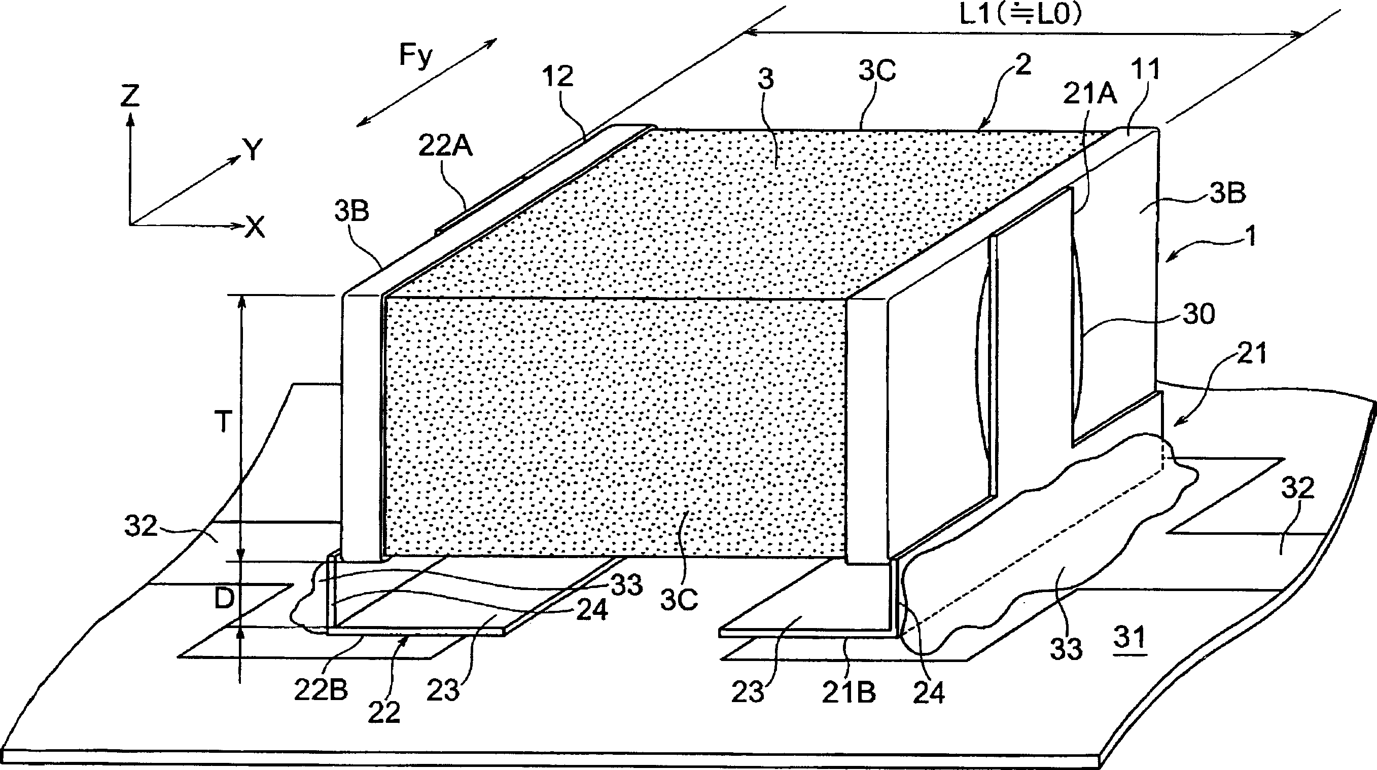
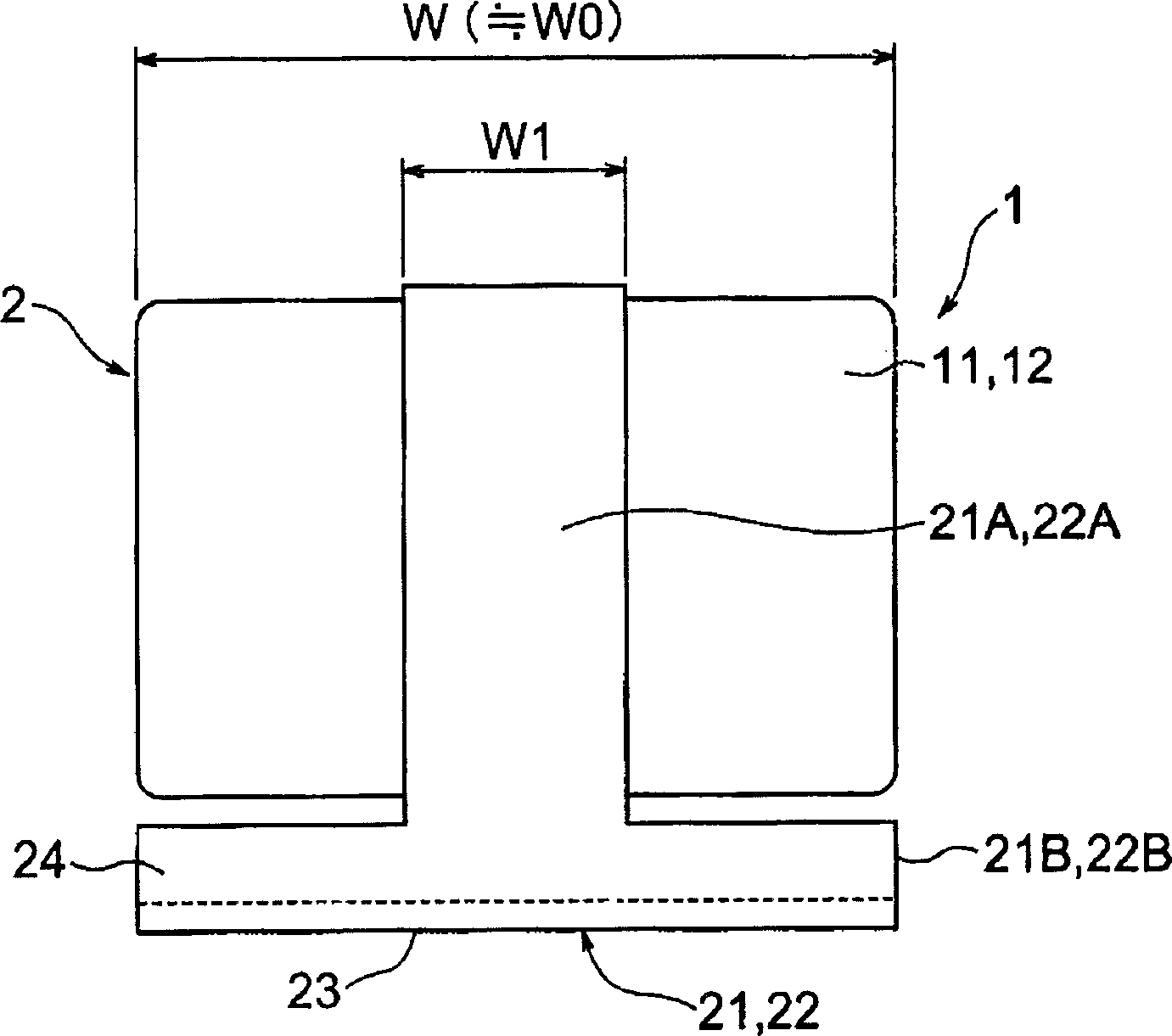
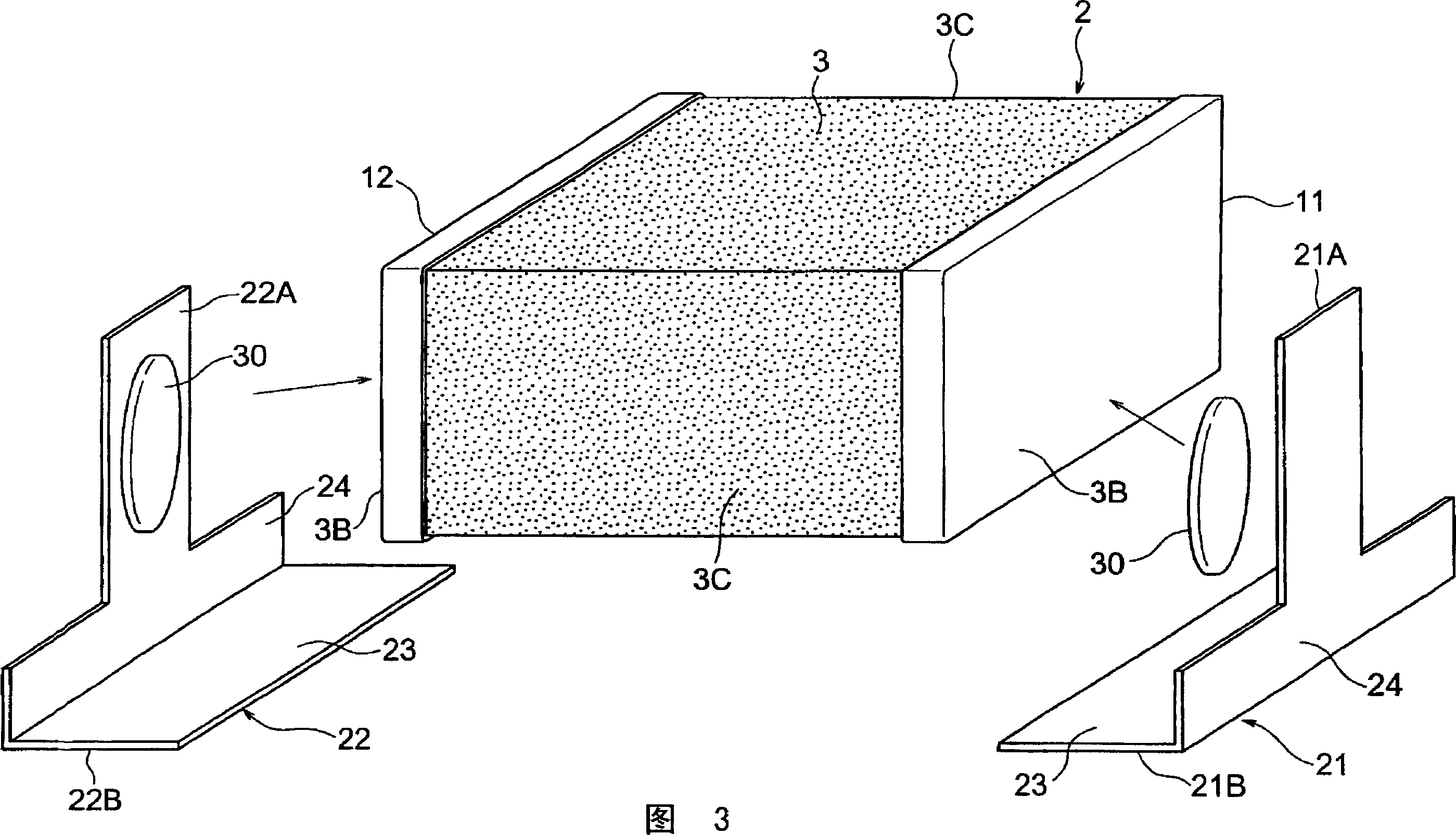
[0081] The multilayer capacitor 1 of the electronic component according to the first embodiment of the present invention is as Figure 1 to Figure 5 shown. This capacitor 1 has a capacitor element (hereinafter also simply referred to as an element) 2 . This element 2 has a dielectric main body (element main body) 3 as a main component, which is a cuboid-shaped sintered body obtained by sintering a laminate in which a plurality of ceramic green sheets are stacked.
[0082] Such as Figure 5 As shown, a ceramic layer 3A and inner conductor layers 4, 5 are built into the dielectric body 3 of the component 2 . The internal conductor layers 4 and 5 are arranged alternately in the stacking direction (also referred to as “height direction”) Z with the ceramic layer 3A interposed therebetween. The number of stacked inner conductor layers 4 and 5 is not particularly limited, for example, about 100 layers.
[0083] The centers of these internal conductor layers 4 and 5 are arranged ...
no. 2 approach
[0105] Hereinafter, as the multilayer capacitor 1a of the electronic component according to the second embodiment of the present invention, as Figure 6 and Figure 7 shown. In addition, the same reference numerals are assigned to the same members as those already described in the first embodiment, and overlapping descriptions are omitted.
[0106] The capacitor 1 a of the present embodiment also has substantially the same structure as the capacitor 1 of the first embodiment. However, if Figure 6 and Figure 7 As shown, according to the present embodiment, the external terminals 21 and 22 each have a pair of element support portions 25A and 25A. A pair of element support portions are located on both sides of each terminal connection portion 21A, 22A, and are formed by bending at substantially right angles to each terminal connection portion 21A, 22A.
[0107] These element support portions 25A are bent parallel to the external connection portions 21B, 22B, and maintain a...
no. 3 approach
[0113] Hereinafter, as the multilayer capacitor 1 of the electronic component according to the third embodiment of the present invention, as Figure 8 and shown in Figure 9. In addition, the same reference numerals are assigned to the same members as those already described in the first embodiment, and overlapping descriptions are omitted.
[0114] This embodiment also has substantially the same configuration as the first embodiment, and achieves the same effects. However, if Figure 8 As shown in FIG. 9 , according to the present embodiment, the external connection portions 21B, 22B are bent in a step shape to form an element support portion 25B. The element support portion 25B has substantially the same width as the external connection portions 21B and 22B. The bottom surfaces of the terminal electrodes 11 and 12 are placed on the element supporting portion 25B.
[0115] That is, although this structure is different from that of the second embodiment, since the element s...
PUM
 Abstract
Description
Claims
Application Information