Stent

A dilator and device shaft technology, applied in the field of dilators, can solve the problems of Y dilators that cannot be transplanted into bifurcated blood vessels, polygons that cannot open larger, and cannot enter into side branches, etc.

Inactive Publication Date: 2004-09-29
KANEKA CORP
View PDF6 Cites 13 Cited by
  • Summary
  • Abstract
  • Description
  • Claims
  • Application Information

AI Technical Summary

Problems solved by technology

[0018] However, there is a disadvantage that the Y dilator cannot be transplanted to the above-mentioned bifurcated vessels.
That is, when the Y dilator is transplanted, even if the stent of the other dilator supply catheter is passed and expanded through the polygon forming the closed strut gap toward the side branch vessel, the polygon cannot be expanded because the perimeter of the polygon is limited. Larger opening, so there is a disadvantage of not being able to enter side branches
In order to solve it, it is also considered to increase the area of ​​the polygon, but this will sacrifice the structure (scaffold) like the open type

Method used


Image

  • Stent
  • Stent
  • Stent

Examples


Embodiment Construction

[0102] Embodiments of the dilator of the present invention will be described below with reference to the accompanying drawings, but the present invention is not limited thereto.

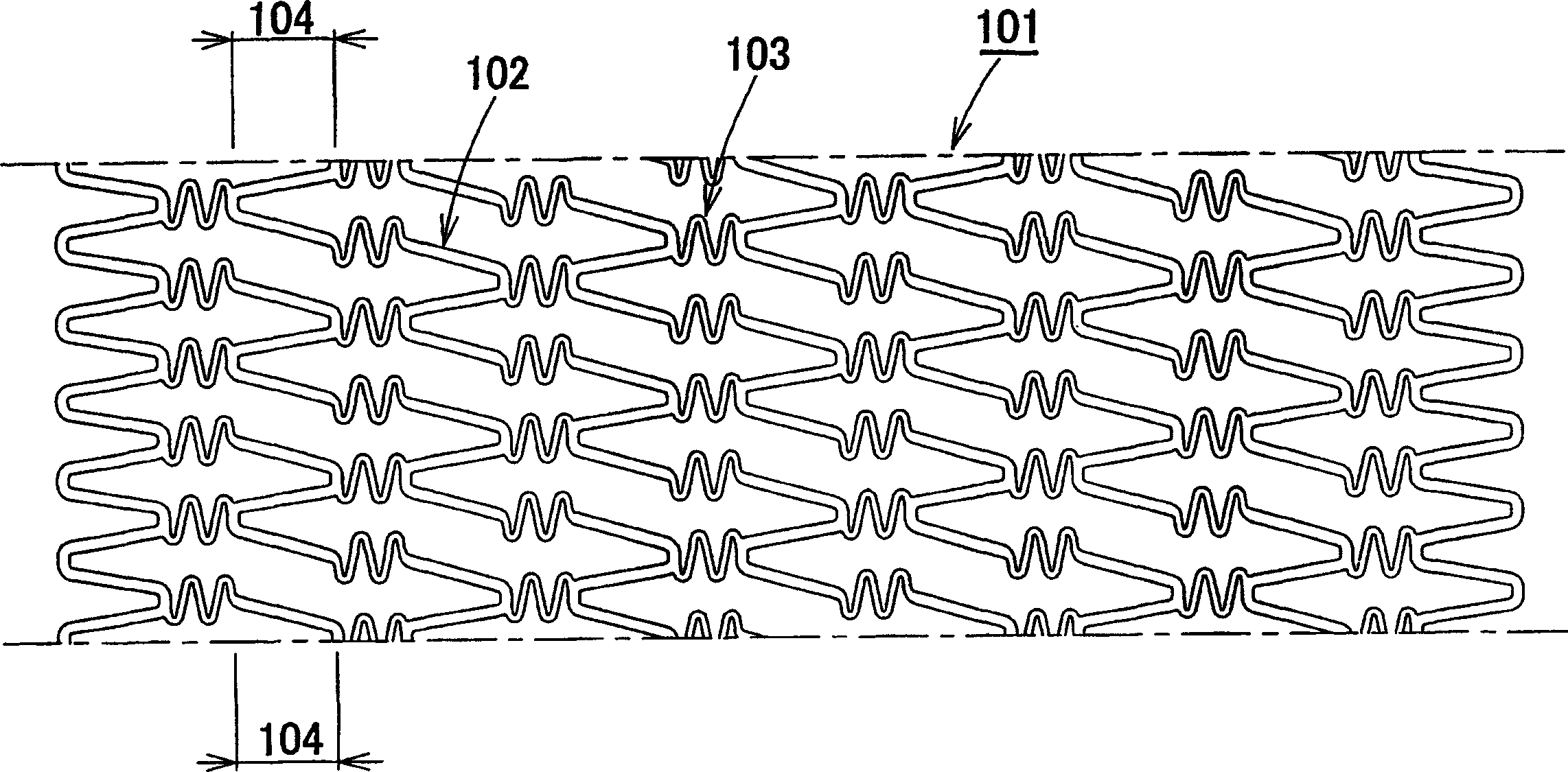
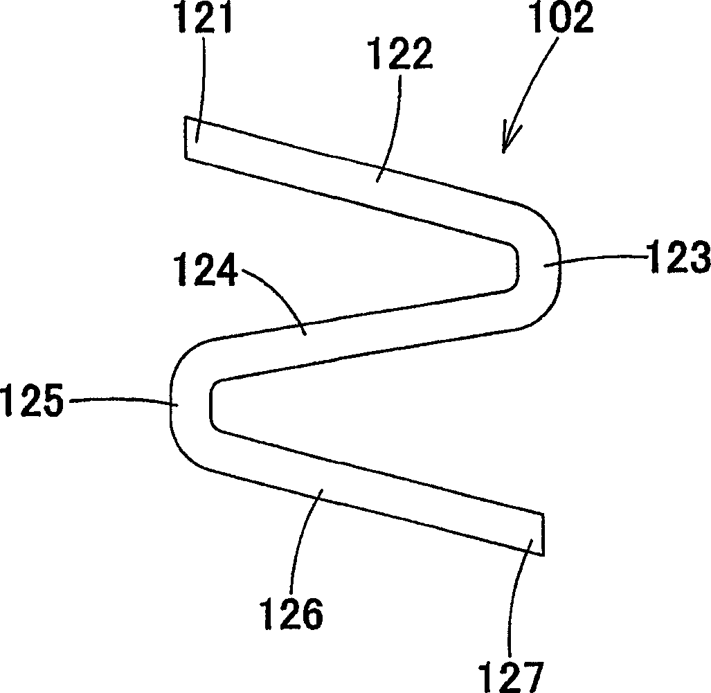
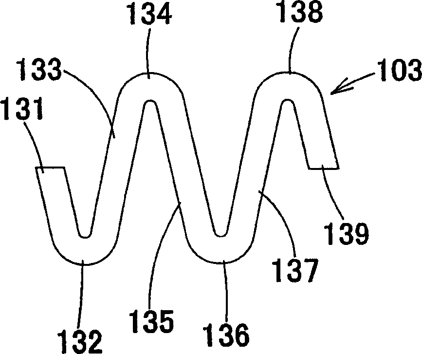
[0103] Figure 1 to Figure 5 represents a dilator according to a first embodiment of the first aspect of the invention, figure 1is a developed view of the dilator 101. The dilator 101 is formed into a roughly tubular body, and can be extended outward in the radial direction of the tubular body, and is composed of a roughly wave-shaped structure unit 102 that can be extended in the circumferential direction and a roughly wave-shaped structure unit 103 that can be stretched in the axial direction. The roughly corrugated structural units 102 that can be stretched are arranged in the general circumferential direction of the dilator and are not directly connected to each other, and the six axially extensible roughly corrugated structural units 103 are not directly connected to each other in the circumfe...


PUM


Abstract

The present invention provides a stent which is flexible in the axial direction prior to the expansion of the stent, which shows no contraction in the axial length of the stent during expansion of the stent, which has an extremely large resistance to forces exerted by contracting blood vessels after expansion, which can cause uniform expansion of the struts of the stent, and in which there is no problem of the end portions of the stent warping to a greater diameter than the central portion of the stent at the time of expansion, furthermore a stent in which the size of the basic cells that constitute the stent is reduced so that bulging of endothelial cells of vascular tissues into the inside of the stent is suppressed, furthermore a stent which allows Y stenting into branched blood vessels while maintaining a high radial force and superior scaffold properties.

Description

technical field [0001] The present invention relates to a dilator to be placed or implanted in a vessel tissue in the body, for example, a dilator to be placed or implanted in a blood vessel in order to prevent restenosis of the narrowed or occluded part of the blood vessel after the dilation. Background technique [0002] The so-called dilator refers to a medical device placed there to maintain the size of the lumen to expand the stenosis or occlusion in order to treat various diseases caused by the stenosis or occlusion of blood vessels or other lumens in the living body. Among them, there are coils made of a single linear metal or polymer material, metal tubes are cut and processed by laser, linear components are assembled by laser welding, and multiple linear metals are braided. . These are disclosed in JP-A-8-332230. [0003] These are divided into those that are expanded by a stent fitted with a dilator and those that are self-expanding by externally removing a membe...

Claims


Application Information

Patent Timeline
Patent Type & Authority Applications(China)
IPC IPC(8): A61F2/06A61F2/82A61F2/856A61F2/91A61F2/915
CPCA61F2/91A61F2002/9155A61F2002/91525A61F2002/91558A61F2/856A61F2002/91533A61F2002/821A61F2/915A61F2002/065A61F2230/0054A61F2/82A61L27/56A61F2/07
Inventor 中野良二前田博巳三木章伍
Owner KANEKA CORP
Why Eureka
Try Eureka