
Adsorption technique

A technology and adsorption tower technology, applied in the field of gas separation and purification, high-efficiency adsorption technology

Inactive Publication Date: 2004-10-27
SHANGHAI SUPEZET ENG TECH CO LTD
View PDF0 Cites 12 Cited by
  • Summary
  • Abstract
  • Description
  • Claims
  • Application Information

AI Technical Summary

Problems solved by technology

During the adsorption process, the heat of adsorption is continuously removed by the built-in cooler

Method used


Image

  • Adsorption technique
  • Adsorption technique

Examples


Embodiment Construction

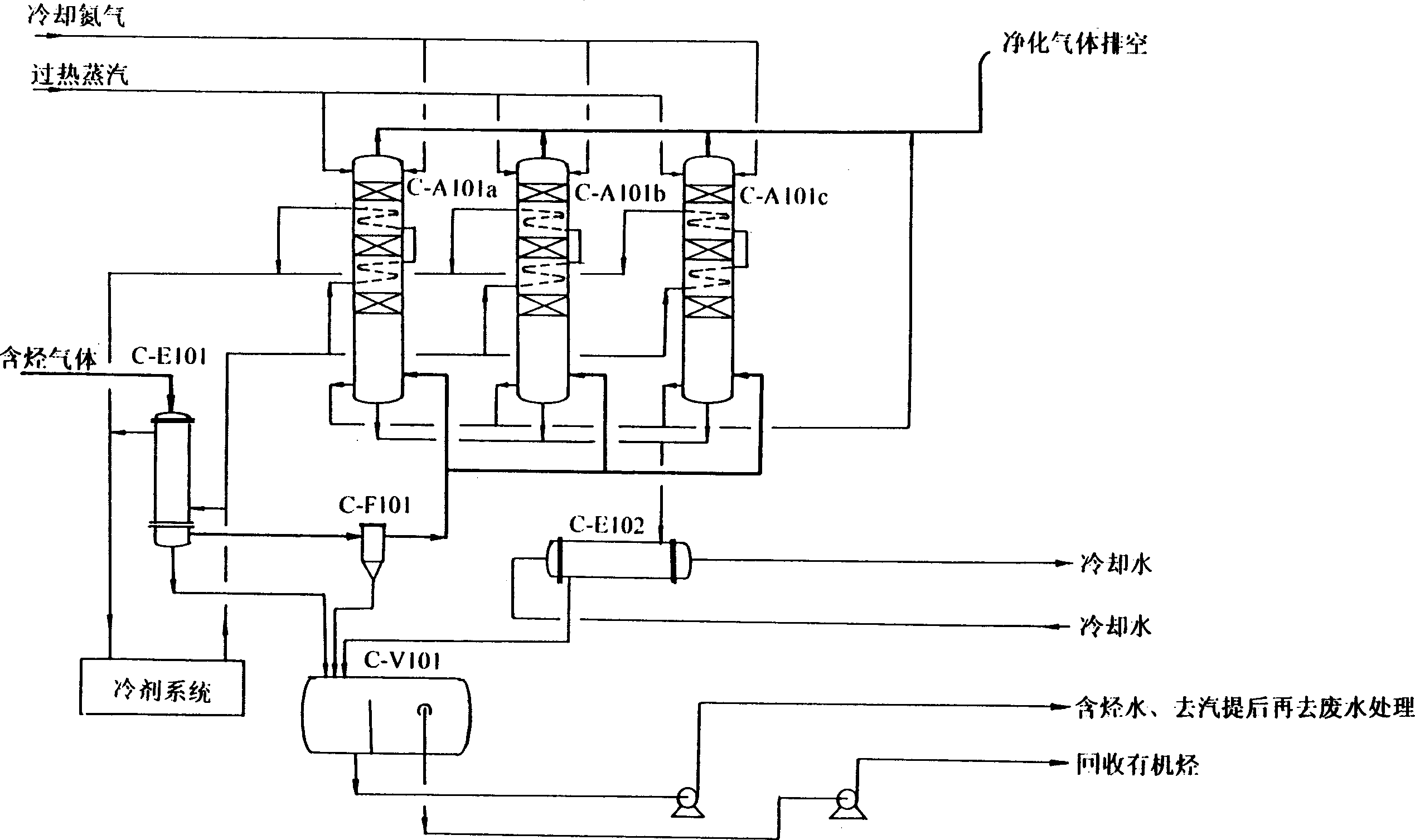
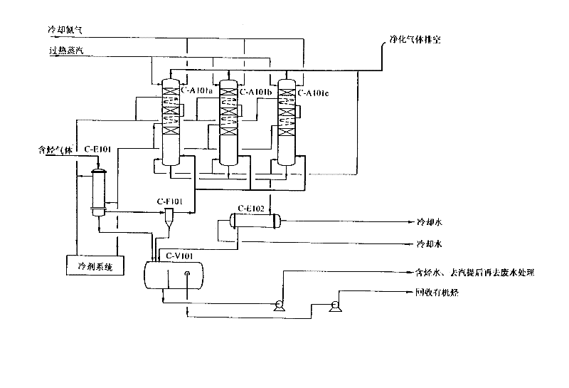
[0009] Refer to the attached figure, the pollutant gas containing organic hydrocarbons (with a certain pressure, if the atmospheric pressure gas or the gas that is not enough to overcome the resistance of the adsorbent bed and the system, a supercharger should be added to the system) first enter the condensing cooler C -E101, where some organic hydrocarbons (such as aromatics, etc.) are condensed and flow into the oil-water separation tank C-V101. After the uncondensed pollutant gas passes through the demister C-F101, it flows into the activated carbon adsorption tower C-A101 system. In this example, three identical adsorption towers are set up. The adsorption gas only enters one of them by switching the valve, for example, At the bottom of C-A101a, through the multi-layer activated carbon fixed bed and built-in cooler, organic hydrocarbons are adsorbed by the activated carbon, and the adsorption heat is also continuously removed through the built-in cooler, so that the activated ...


PUM


Abstract

An adsorption technology features that its system is composed of more than one adsorption tower and condenser. All the adsorption towers are parallelly connected to gas-material pipeline and each adsorption tower has a built-in cooler. Said adsorption technology includes condensing part of raw organic hydrocarbon, oil-water separation, flowing rest of organic hydrocarbon in adsorption tower, multi-layer adsorbing, cooling for optimal adsorption, switching to next adsorption tower while thermal regeneration for this adsorption tower, and introducing cooling gas to bed and cooling medium to cooler.

Description

Technical field: [0001] The invention relates to an efficient adsorption process for improving the adsorption rate and saturation rate. It belongs to gas separation and purification technology. Background technique: [0002] The adsorption process is more suitable for purifying exhaust gas containing multiple pollutants, especially exhaust gas containing organic matter. It can purify exhaust gas containing organic matter to a very low concentration (even below the ppm level). [0003] In the adsorption process, the gas molecules move to the surface of the adsorbent (solid surface, such as molecular sieve, aluminum silicate, silica gel, activated carbon, etc.), their molecular motion is greatly reduced, and heat is released. Therefore, the adsorption process is always exothermic. On the contrary, desorption is the reverse process of adsorption, and heat must be supplied before desorption can continue. Therefore, desorption is actually a heating process. In industry, superheated st...

Claims


Application Information

Patent Timeline
IPC IPC(8): B01D53/04
Inventor 杨德芝孙鉏源
Owner SHANGHAI SUPEZET ENG TECH CO LTD
Learn More