Two-way two-tube positive excitation converter topology

A technology of forward converter and topology, which is applied in the field of dual-circuit and dual-tube forward converter topology, which can solve the problems of bridge arm direct connection and low reliability, and achieve low switching loss, high reliability, and reduced volume effect

Inactive Publication Date: 2004-11-10
NANJING UNIV OF AERONAUTICS & ASTRONAUTICS
View PDF0 Cites 20 Cited by
  • Summary
  • Abstract
  • Description
  • Claims
  • Application Information

AI Technical Summary

Problems solved by technology

However, in high-voltage, medium- and high-power applications, the commonly used topology is the full-bridge converter. This type of converter has a bridge arm through problem and low reliability. It must take special measures in the control, otherwise it will cause serious consequences.

Method used


Image

  • Two-way two-tube positive excitation converter topology
  • Two-way two-tube positive excitation converter topology
  • Two-way two-tube positive excitation converter topology

Examples


Embodiment Construction

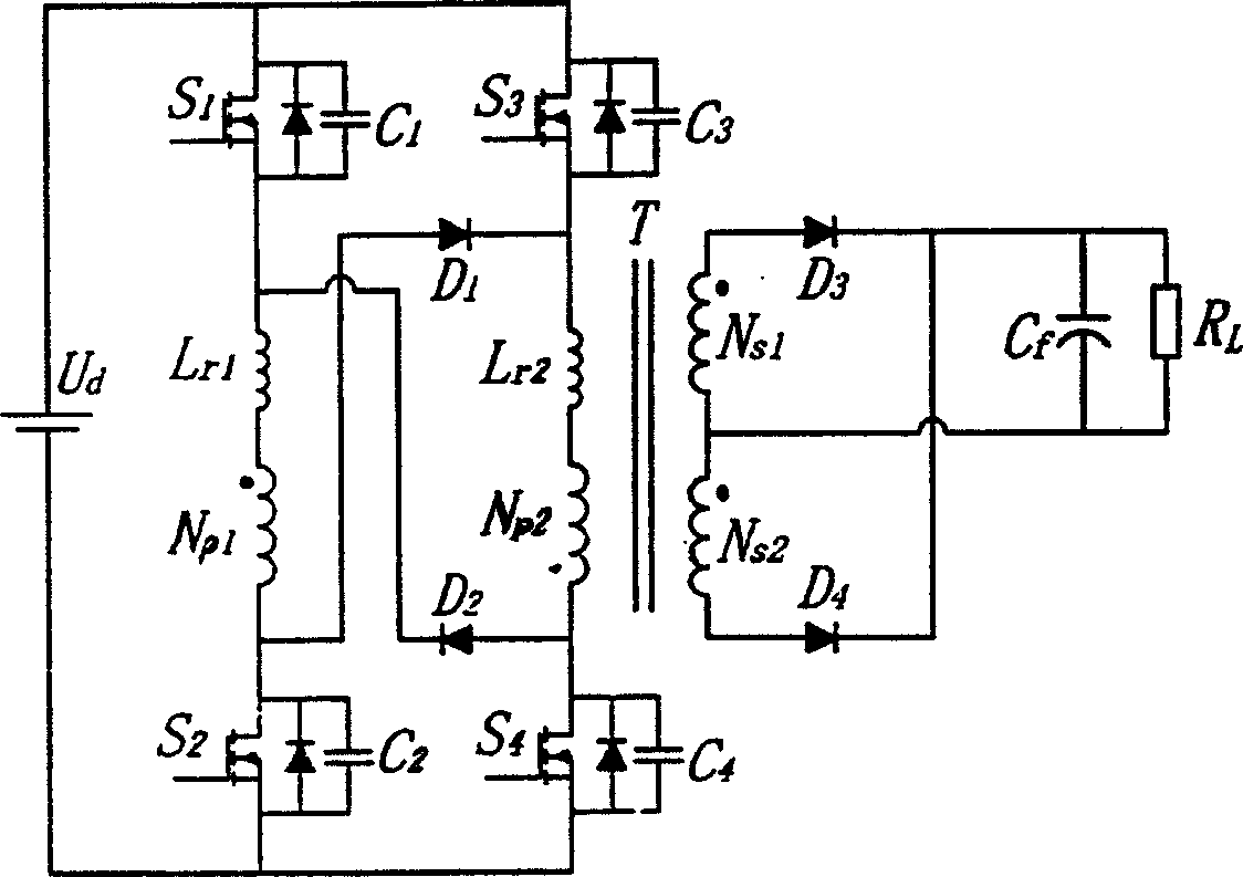
[0019] Specific embodiments of the present invention will be described based on the above-mentioned drawings. Depend on figure 1 It can be seen that the composition of the circuit of the present invention is that the first power switch tube S 1 , inductance L r1 , Main power transformer T primary winding N p1 , the second power switch tube S 2 sequentially connected in series to form a series structure circuit; the third power switch tube S 3 , inductance L r2 , Main power transformer T primary winding N p2 , the fourth power switch tube S 4 In turn, they are connected in series to form another series structure circuit, and the two series structure circuits are connected in parallel to the power supply U at the same time. d ends. clamping diode D 1 Forwardly connected to the second power switch tube S of the first series structure circuit 2 The anode and the third power switch tube S of the second series structure circuit 3 The negative pole of the clamping diode D ...


PUM


Abstract

The invention relates to a two-way two-tube forward converter topology, its main circuit composed of power supply, four power diodes, two primary side clamping diodes, two serial capacitances, a main power transformer composed of primary winding and secondary winding with a secondary side composed of a rectifier with two rectifier diodes and an output filter capacitance. It remains the advantages of low primary-side voltage stress of a two-way two-tube forward converter, no direct turn-on of bridge arm, high reliability, etc; compared with general two-way two-tube forward converters, it has only two clamping diodes and simple structure; it adopts magnetic integration technique of transform, further reducing the bulk and enhancing power density of transform. It not only implements zero voltage turn-on and turn-off, but also basically eliminating voltage peak of diodes in the secondary rectifier by the clamping action of filter capacitance, having very high efficiency.

Description

technical field [0001] The topology of the two-way two-tube forward converter of the invention belongs to the converter. Background technique [0002] Switching power supply is being more and more widely used in various fields of national production due to its remarkable advantages such as high efficiency, small size and light weight. With the widening of the application range and the increase of electrical equipment, higher requirements are put forward for the performance of the power supply system. How to ensure the high reliability of the power supply, how to further increase the power density of the converter, and how to ensure high efficiency while increasing the frequency are the key issues of current research. In terms of reliability, the dual-transistor forward converter has been widely used due to its low voltage stress on the primary switching tube, its inherent ability to resist bridge arm shoot-through, and its high reliability. Through the parallel and series ...

Claims


Application Information

Patent Timeline
Patent Type & Authority Applications(China)
IPC IPC(8): H02M3/335H02M7/5387
Inventor 王慧贞龚春英周平森严仰光
Owner NANJING UNIV OF AERONAUTICS & ASTRONAUTICS
Why Eureka
Try Eureka