Optical fiber preform and manufacturing method therefor

A technology for optical fiber preforms and glass rods, which is applied to manufacturing tools, glass manufacturing equipment, glass production, etc., can solve the problems of increased processing times, increased optical fiber manufacturing costs, and increased optical fiber preform manufacturing costs.

Active Publication Date: 2004-12-01
FUJIKURA LTD
View PDF4 Cites 5 Cited by
  • Summary
  • Abstract
  • Description
  • Claims
  • Application Information

AI Technical Summary

Problems solved by technology

However, in this case, since the content of hydroxyl groups in the central glass rod must be reduced as low as possible, the costs for the dehydration treatment of the central glass rod increase, and thus also the manufacturing costs of the optical fiber
[0016] In the method of reducing the hydroxyl group content in the outer cladding formed on the outer surface of the central glass rod, a problem encountered is an increase in the number of treatments such as etching to remove a part of the outer cladding where hydroxyl groups exist.
[0017] In addition, using the method of drawing the central glass rod in an electric furnace may encounter problems with air bubbles or foreign particles in the central glass rod unless the preform is fire polished before further fine glass particle external deposition process
[0018] As mentioned above, when using any of the conventional methods for reducing the hydroxyl content in the optical fiber preform, the problem encountered is that the manufacturing cost of the optical fiber preform increases due to the increase in the number of processes or the decrease in production capacity.

Method used


Image

  • Optical fiber preform and manufacturing method therefor
  • Optical fiber preform and manufacturing method therefor
  • Optical fiber preform and manufacturing method therefor

Examples


example 1

[0066] A glass rod including a core and a cladding portion was formed using a VAD (Vapor Axial Deposition) method, and drawn to obtain a central glass rod with a diameter between 23-34 mm.

[0067] Afterwards, use the same process to obtain multiple central glass rods.

[0068] The surface of each central glass rod was fire-polished, wherein an oxyhydrogen flame was emitted from a burner moving along the longitudinal direction of each glass rod.

[0069] The moving speed of the burner was set at 30 mm / min.

[0070] As shown in Table 1, several sets of different values ​​(Conditions A-E) were set for the temperature of the oxyhydrogen flame, the flow rate of oxygen supplied to the burner, and the flow rate of hydrogen supplied to the burner.

[0071] Next, fine glass grains are deposited on the outer surface of each central glass rod, and each central glass rod with deposited fine glass grains is dehydrated and vitrified in an electric furnace to form an outer cladding, thereb...

example 2

[0082] A glass rod including a core and a cladding portion was formed using a VAD method, and the glass rod was drawn to obtain a central glass rod with a diameter of 23-34 mm.

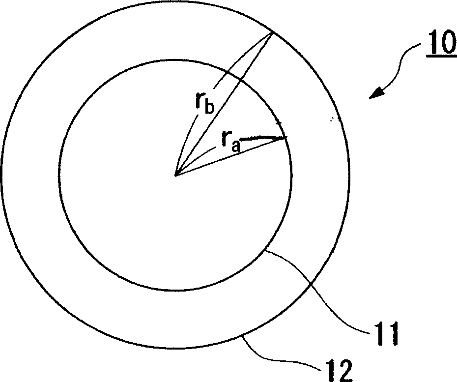
[0083] Using the above-mentioned central glass rod, in the same manner as in Example 1, under conditions A-1 to A-3, and B-1 to B-3 shown in Table 2, optical fiber preforms of cylindrical shape were obtained. In Table 2, r a Indicates the radius of the central glass rod, r b Indicates the radius of the fiber preform.

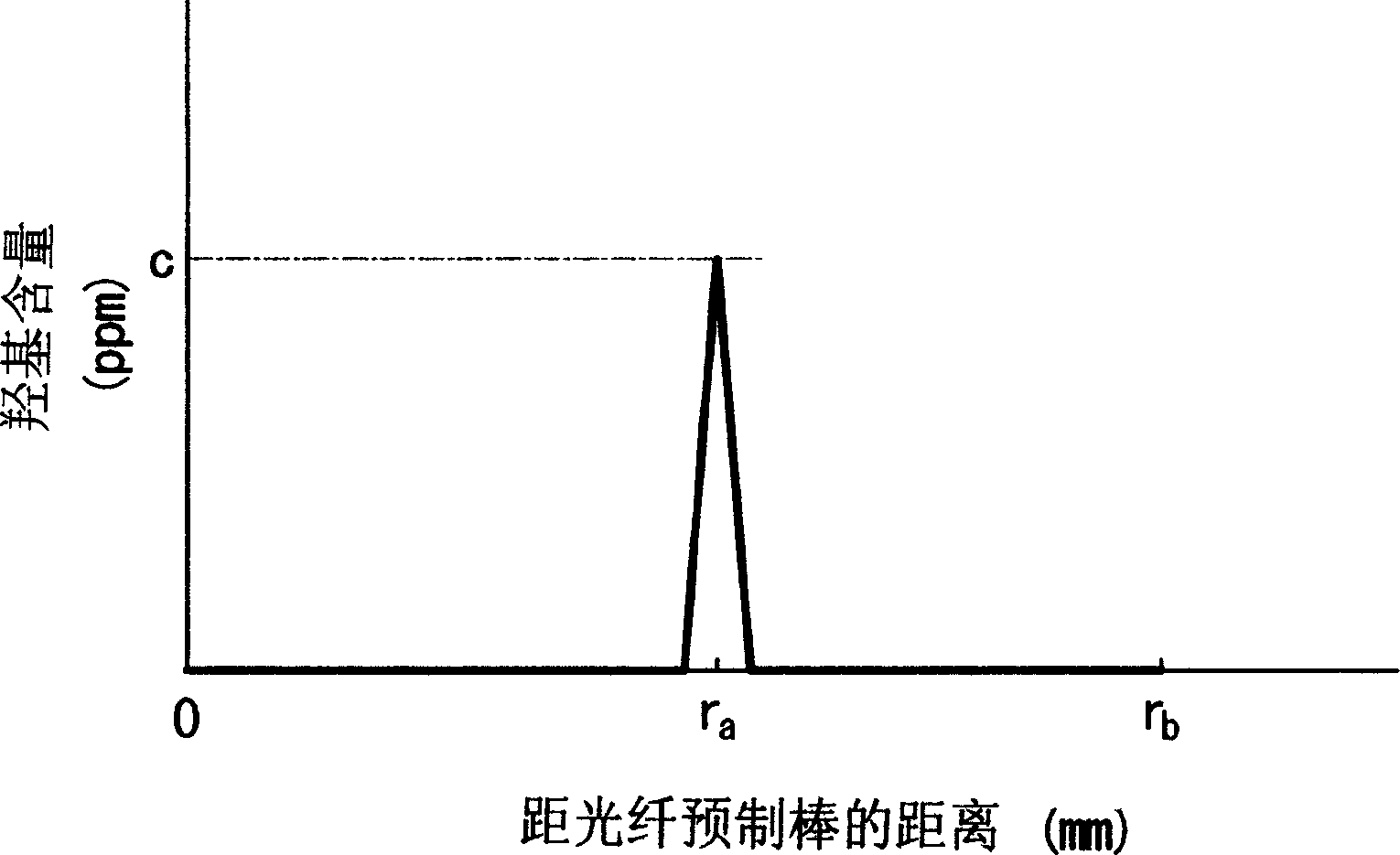
[0084] Maximum hydroxyl content

c(ppm)

r a / r b

r a / r b / c

Condition A-1

130

0.248

0.0019

Condition A-2

130

0.352

0.0027

Condition A-3

130

0.416

0.0032

Condition B-1

180

0.320

0.0018

Condition B-2

180

0.368

0.0020

Condition B-3

180

0.496

0.0028

[0085] ...

example 3

[0089] Central glass rods were produced in the same manner as in Example 2, and using these central glass rods, cylindrical optical fiber preforms were obtained under conditions C, D-1, D-2 and E shown in Table 3.

[0090] Maximum hydroxyl content c(ppm)

r a / r b

r a / r b / c

Condition C

50

0.288

0.006

Condition D-1

32

0.288

0.009

Condition D-2

35

0.416

0.012

Condition E

20

0.288

0.014

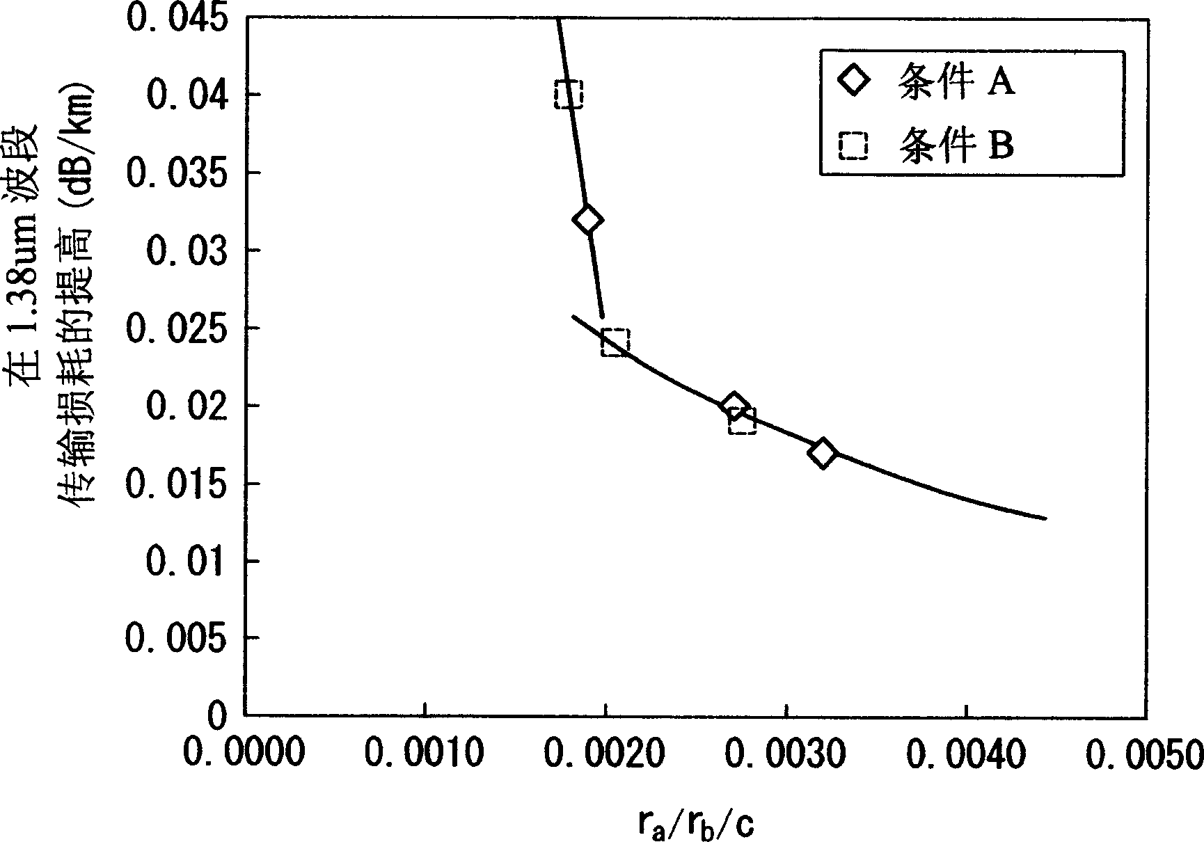
[0091] Optical fibers were formed by drawing the optical fiber preforms produced under the conditions shown in Table 3. The drawing speed was set at 1000 m / min.

[0092] Measure the transmission loss in the 1.38um band caused by hydroxyl in the optical fiber. Measurement results such as Figure 4 shown.

[0093] Such as Figure 4 As shown, even when the ratio r a / r b When / c is set to be greater than 0.01, it is also impossible to reduce t...


PUM

PropertyMeasurementUnit
diameteraaaaaaaaaa
thicknessaaaaaaaaaa

Abstract

A method for manufacturing an optical fiber preform includes a process A of applying flame polishing to a center glass rod, a process B of determining a ratio ra / rb, which is a ratio of a radius ra of the center glass rod expressed in millimeters with respect to a radius rb of a target optical fiber preform expressed in millimeters, based on a refractive index profile of a target optical fiber preform, and a process C of determining an amount of fine glass particles to be deposited on the center glass rod so that a ratio ra / rb / c falls within a range from 0.002 to 0.01, where 'c' is a maximum value of hydroxyl group concentration expressed in ppm in the vicinity of a boundary between the center glass rod and an outer layer, which is formed by depositing fine glass particles on the center rod and by being vitrified.

Description

technical field [0001] The present invention relates to an optical fiber preform for manufacturing a single-mode optical fiber and a method for manufacturing the optical fiber preform. Specifically, the present invention relates to an optical fiber preform for manufacturing a single-mode optical fiber capable of wavelength division multiplexing over a wide wavelength band, and to a method of manufacturing such an optical fiber preform. [0002] This application claims priority from the following Japanese patent applications: Japanese Patent Application No. 2003-131729 filed on May 9, 2003, Japanese Patent Application No. 2003-192934 filed on July 7, 2003, and Japanese Patent Application No. 2003-192934 filed on April 2, 2004. Japanese Patent Application No. 2004-109698 filed on Japan, the contents of which are cited herein by reference. Background technique [0003] In recent years, due to the rapid popularization of the international Internet and internal Internet, the dem...

Claims


Application Information

Patent Timeline
Patent Type & Authority Applications(China)
IPC IPC(8): C03B37/018C03B37/012C03B37/014C03C13/04C03C25/68
CPCC03B37/014C03B2201/04C03B37/01237Y02P40/57
Inventor 后藤孝和山田成敏
Owner FUJIKURA LTD
Why Eureka
Try Eureka