Projecting exposure apparatus

An exposure device and projection technology, which is applied in the direction of photolithography exposure device, printing device, microlithography exposure equipment, etc., can solve problems such as the difficulty in making the first imaging optical system, and achieve improved adjustment, improved precision, and improved exposure quality Effect

Inactive Publication Date: 2004-12-01
FUJIFILM CORP
View PDF1 Cites 7 Cited by
  • Summary
  • Abstract
  • Description
  • Claims
  • Application Information

AI Technical Summary

Problems solved by technology

[0014] However, the above performances (MTF performance, distortion performance, accuracy of imaging magnification) are related to each other. If the accuracy of imaging magnification is improved, the MTF performance and distortion performance will be reduced. Therefore, it is difficult to manufacture the first imaging optical system so that the Each performance becomes more than the specified performance

Method used


Image

  • Projecting exposure apparatus
  • Projecting exposure apparatus
  • Projecting exposure apparatus

Examples


Embodiment Construction

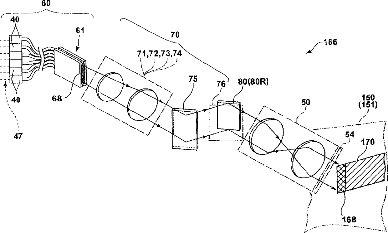
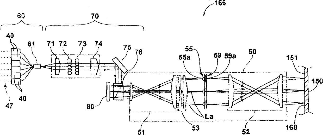
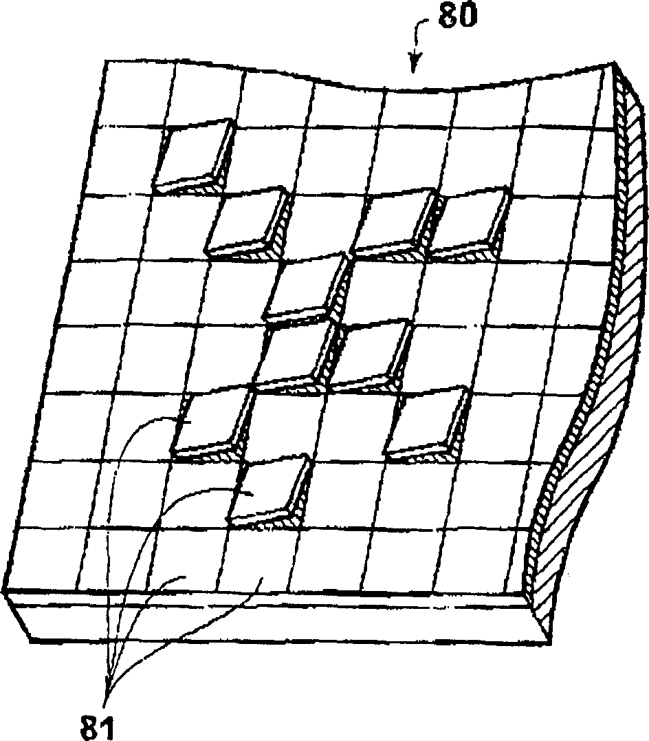
[0052] Next, embodiments of the projection exposure apparatus of the present invention will be described with reference to the drawings. FIG. 1 is a conceptual diagram showing a schematic structure of an exposure head mounted on a projection exposure apparatus, FIG. 2 is a side view showing the structure of the exposure head along an optical path propagating in the exposure head, and FIG. 3 is a schematic structure of a DMD. stereogram.

[0053] The projection exposure apparatus of the embodiment of the present invention has: a DMD 80 as a spatial light conversion unit, which modulates the light emitted from the light source unit 60 as a light source and incident through the DMD irradiation optical system 70 according to a predetermined control signal, A plurality of micro-mirrors 81 as the pixel portion are arranged in a 2-dimensional shape, and the light is spatially modulated by the plurality of micro-mirrors 81;

[0054] The first imaging optical system 51 is an imaging o...


PUM

PropertyMeasurementUnit
lengthaaaaaaaaaa
thicknessaaaaaaaaaa
transmittivityaaaaaaaaaa

Abstract

To obtain a projection aligner in which the extinction ratio of a two-dimensional pattern projected onto a photosensitive material is enhanced. When a two-dimensional pattern of a light spatially modulation through a DMD 80 passes through an image side telecentric first image formation optical system 51 to form an image, magnification of the image is adjusted through a magnification adjusting optical system 53. Subsequently, an incident light emitted from a light source unit 60 and passed through a DMD irradiation optical system 70 is subjected to spatial light modulation through a DMD 80 and a two-dimensional pattern of a light spatially modulation through the DMD 80 is passed through the first image formation optical system 51, the magnification adjusting optical system 53, a microlens array 55, an aperture array 59 and a second image formation optical system 52 before being projected onto a photosensitive material 150 in order to expose the photosensitive material 150.

Description

technical field [0001] The present invention relates to a projection exposure device, in particular, to a projection exposure device that projects a two-dimensional pattern that has undergone spatial light modulation onto a photosensitive material through an imaging optical system that is telecentric on one side of the image for exposure. Background technique [0002] Conventionally, it is known to use a spatial light modulator that spatially modulates incident light according to a predetermined control signal, project a two-dimensional pattern spatially modulated by the spatial light modulator onto a photosensitive material, and expose the photosensitive material. Projection exposure device. It is also known that a digital micromirror device (hereinafter referred to as DMD) in which a plurality of micromirrors capable of changing inclination angles are arranged in a two-dimensional shape (for example, 1024×756) is used as the spatial light modulator. Projection exposure ap...

Claims


Application Information

Patent Timeline
Patent Type & Authority Applications(China)
IPC IPC(8): G02B13/24B41J2/45G02B26/08G03F7/20H01L21/027
CPCB41J2/451G02B26/0833G03F7/70275G03F7/70291G03F7/70258G03F7/20
Inventor 石川弘美
Owner FUJIFILM CORP
Why Eureka
Try Eureka