Connection structure of connection of floor beam and steel pipe concrece pole and construction method thereof

A technology for concrete-filled steel tubular columns and concrete beams, which is applied in the directions of structural elements, building components, building structures, etc., can solve the problems of difficulty in centering upper and lower columns, inconvenient construction, and increase the self-weight of the structure, so as to avoid the problem of centering upper and lower steel tubes. , good economic benefits, the effect of reducing the cost of the structure

Inactive Publication Date: 2005-01-05
SOUTH CHINA UNIV OF TECH
View PDF0 Cites 29 Cited by
  • Summary
  • Abstract
  • Description
  • Claims
  • Application Information

AI Technical Summary

Problems solved by technology

[0008] 1) The mechanical properties of joints and the simplicity and economy of construction cannot be both: some joint types, such as reinforced ring type joints, have good mechanical properties and high overall stiffness of joints, but the amount of materials is large and the construction is complicated; some joint types, For example, the anchor plate joint has simple structure, convenient construction, and saves materials, but its mechanical properties are not ideal; another example is the shear ring beam joint, which has outstanding construction and economic advantages, but its joint stiffness is limited. , poor performance under complex stress conditions;
[0009] 2) Affect the appearance and use of the building: the structure of the joints of the cast-in-place floor beams and slabs often conflicts with the appearance and use functions of the building, and makes the layout of the floor beams and slabs inflexible, such as the complicated layout of the beam system of the double-beam joints, and the The single beam joint makes the width of the floor beam too large, which not only increases the weight of the structure but also causes waste of materials, and affects the beauty of the floor

Method used


Image

  • Connection structure of connection of floor beam and steel pipe concrece pole and construction method thereof
  • Connection structure of connection of floor beam and steel pipe concrece pole and construction method thereof
  • Connection structure of connection of floor beam and steel pipe concrece pole and construction method thereof

Examples


Embodiment Construction

[0040] The present invention will be further described below in conjunction with accompanying drawing.

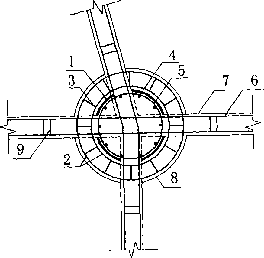
[0041] The flow chart of the construction method of the joint structure of the steel pipe concrete column and the floor beam connection of the present invention is as follows figure 2 As shown, the construction steps are as follows:

[0042] ① Hoist the single-layer or multi-layer steel pipe column to the column positioning position of the construction plane;

[0043] ② Hoist the reinforcement cage to the inner node position of the steel pipe, and fix it with a crossbar;

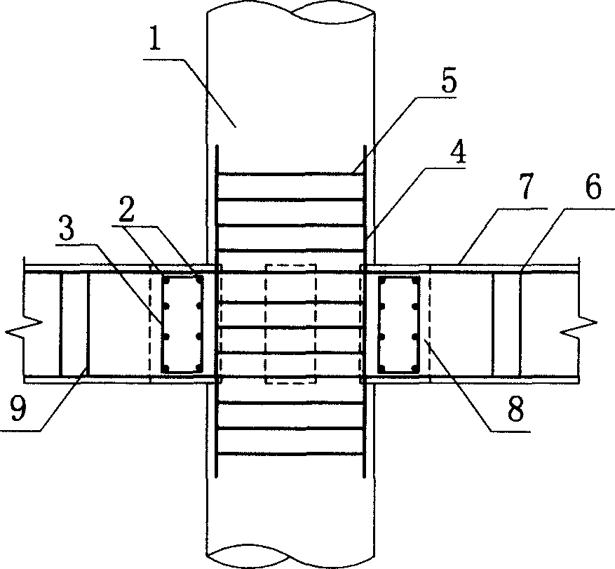
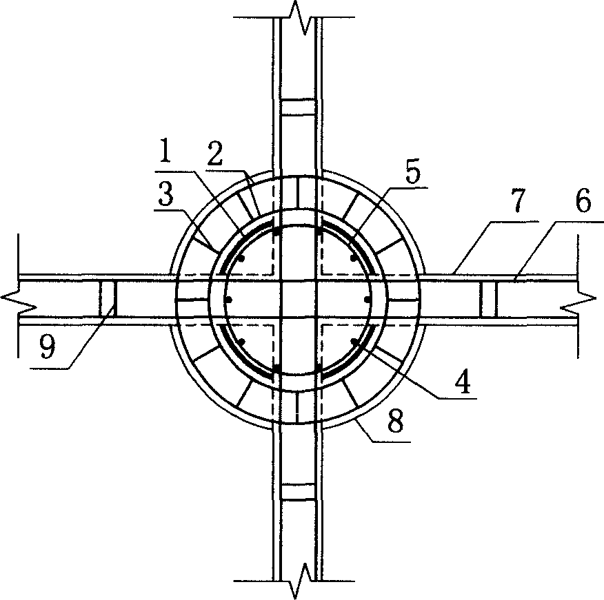
[0044] ③ placing the reinforced skeleton of the annular concrete beam (8) tied on the open space in the formwork of the annular concrete beam (8);

[0045] ④ Pass the beam longitudinal reinforcement (6) of the floor girder (7) through the node area, bind the beam stirrup (9), and install a steel wire mesh at the opening of the steel pipe to prevent the concrete from flowing out of the node area;

[004...


PUM


Abstract

The invention discloses a joint structure at the connection part of steel pipe concrete pile and floor beam and the constructing method. The joint structure includes steel pipe concrete pile, floor beam and ring type concrete beam. The vertical component steel pile and the parallel component floor beam are connected at the joint, the steel pipe is drilled with a aperture at position correspondent to the joint on the floor, thus the beam lengthwise rib of the beam can pass through the steel pile directly; ring type concrete beams are arranged around the steel pipe in the joint area, the steel bar in the ring concrete beam includes ring type beam lengthwise rib which is concentric with the steel pipe concrete pile and radiate ring beam hooping in radius direction; a steel bar cage concentric with the steel pipe is arranged in the pile, which includes vertical pile connection lengthwise rib and parallel pile connection hooping, the anchor in the steel bar cage extension length is decided by the diameter of the steel bar.

Description

technical field [0001] The invention relates to a building structure, in particular to a node structure at the junction of a steel pipe concrete column and a floor beam and a construction method thereof. Background technique [0002] As a composite structure with the advantages of steel structure and concrete structure, CFST column is more and more widely used in engineering. However, as one of the key parts of the structure, the problems of force and structure have not yet been solved. It has been well resolved and has become a "bottleneck" problem restricting the application of CFST columns. [0003] The existing connection structures of steel tube concrete columns and floor beams in the joint area can be divided into two types: column steel tube continuous form and floor beam continuous form. [0004] 1. Nodes in the continuous form of column steel pipes: [0005] The main idea is: keep the steel pipe concrete column connected along the full h...

Claims


Application Information

Patent Timeline
IPC IPC(8): E04B1/18E04B1/58E04C5/01
Inventor 蔡健陈庆军杨春
Owner SOUTH CHINA UNIV OF TECH
Why Eureka
Try Eureka