Phase control focusing ultrasonic transducer array in high internsity

An ultrasonic transducer, high-strength technology, applied in the field of biomedical engineering, can solve the problems of limited work flexibility, harm to patients, heating, etc., and achieve the effects of complete functions, strong grating lobe suppression ability, and common material selection.

Inactive Publication Date: 2005-01-12
SHANGHAI JIAO TONG UNIV
View PDF1 Cites 20 Cited by
  • Summary
  • Abstract
  • Description
  • Claims
  • Application Information

AI Technical Summary

Problems solved by technology

This type of phase-controlled focusing high-intensity ultrasonic transducer array basically overcomes the shortcomings of curved surface self-focusing and acoustic lens focusing ultrasonic transducers, but it not

Method used


Image

  • Phase control focusing ultrasonic transducer array in high internsity
  • Phase control focusing ultrasonic transducer array in high internsity

Examples


Embodiment Construction

[0017] In order to better understand the technical solution of the present invention, a further detailed description will be made below in conjunction with the accompanying drawings.

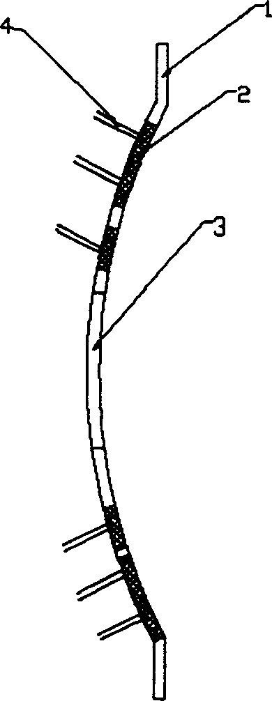
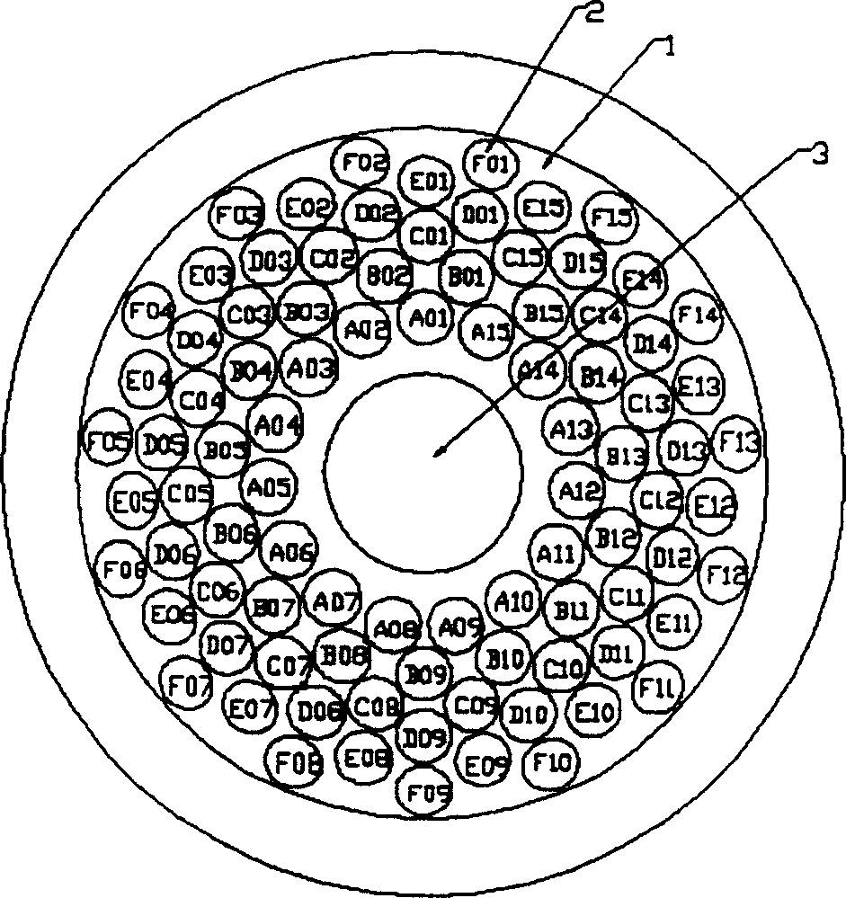
[0018] The structural side view of the phase-controlled focusing high-intensity ultrasonic transducer array designed by the present invention is as follows figure 1 shown. The central opening 3 of the large-aperture rigid spherical crown 1 is the space for positioning the B-ultrasound probe. On the spherical crown 1 outside the central opening 3, multiple layers of circular small holes are discretely distributed, and the array elements 2 are embedded in the small holes. . The geometric radius R of the spherical cap body 1 approaches the maximum scanning depth, that is, the sum of the minimum depth of focus and the axial scanning range. Each array element 2 has an independent electric excitation signal feeder, which is respectively connected to the phase control signal excitation system.

[00...


PUM


Abstract

A high-intensity ultrasonic transducer array which phase-conrol fucusing is composed of a big-aperture rigid spherical crown body with a geometric radium close to maximal scan depth, a centrol hole for installing the probe of ultrasonography B and several small holes distributed in the mode of multi-layer regular ring array with unequal spacings, and several array cells inlaid in said holes. Its advantages are correct location, flexible focusing, small array aperture, and high grating lobe suppressing power and sonic intensity gain.

Description

technical field [0001] The invention relates to a phase-controlled focused high-intensity ultrasonic transducer array, which is applied to a high-intensity focused ultrasonic (HIFU) tumor treatment system and belongs to the technical field of biomedical engineering. Background technique [0002] The high-intensity focused ultrasound transducer is one of the key components of the high-intensity focused ultrasound tumor therapy system. It not only penetrates the ultrasonic energy emitted outside the body into human tissue, but also forms a region with extremely high sound intensity in the target tissue through a certain focusing method - the focal zone. Due to the large amount of energy deposited in the focal area, the instantaneous temperature in the tissue inside is as high as 65°C, and this part of the tissue will appear instantaneous coagulation necrosis, while the tissue outside the focal area is basically not damaged due to only a small amount of energy deposition. So a...

Claims


Application Information

Patent Timeline
IPC IPC(8): A61N7/02
Inventor 陈亚珠白景峰李国伟
Owner SHANGHAI JIAO TONG UNIV
Why Eureka
Try Eureka