
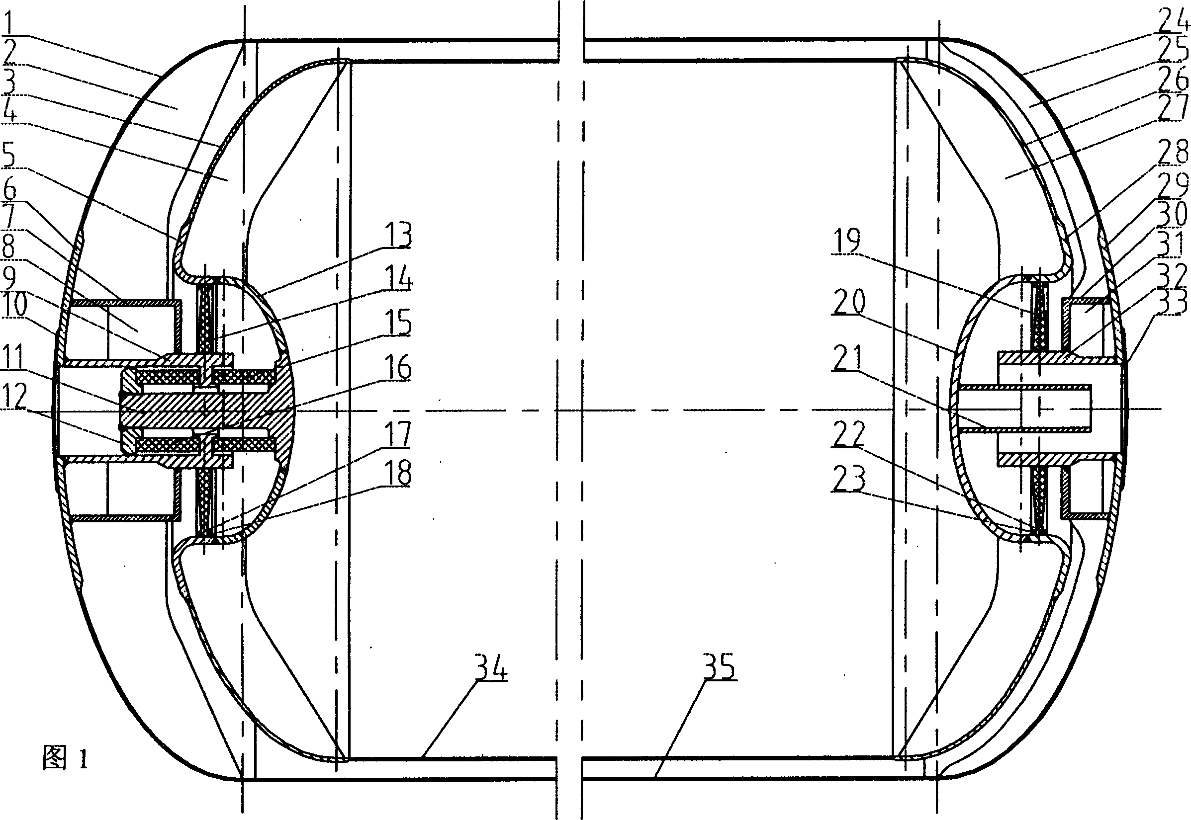
Internal bearing structure of high vacuum multilayer insulation, horizontal low temp LG cylinder

A low-temperature liquefied gas, multi-layer insulation technology, applied in gas/liquid distribution and storage, fixed-capacity gas storage tanks, pressure vessels, etc., can solve the problem of reduced impact resistance, large distance between inner and outer heads, and increased contact gap, etc. problems, to achieve the effect of improving impact resistance, small head gap, and lengthening

Inactive Publication Date: 2005-01-12
SHANGHAI JIAO TONG UNIV +1
View PDF1 Cites 9 Cited by
  • Summary
  • Abstract
  • Description
  • Claims
  • Application Information

AI Technical Summary

Problems solved by technology

In the prior art, the upper and inner support structures of the horizontal low-temperature storage tank currently used at home and abroad include: 1) the heat-insulating pad structure between the inner tank and the shell straight cylinder, but it cannot effectively solve the problem of support leakage caused by the small distance between high-vacuum multi-layer heat insulation; The contradiction of large heat and the damage or interruption of the high-vacuum multi-layer insulation layer caused by the thermal expansion and contraction of the inner tank; 2) The stainless steel casing structure between the inner and outer heads is difficult to manufacture, the distance between the inner and outer heads is large, and the impact resistance is poor , and the heat leakage is relatively large; 3) The structure of the suspension belt cannot effectively solve the problem of the decline in the impact resistance caused by thermal expansion and contraction; 4) The utility model patent of the low-temperature container anti-strong impact support structure with the patent number ZL00216678.X, It is required that the distance between the heads is large and the contact gap increases when the room temperature turns to low temperature, and the impact resistance level decreases

Method used


Image

  • Internal bearing structure of high vacuum multilayer insulation, horizontal low temp LG cylinder

Examples


Embodiment Construction

[0007] The specific implementation of the present invention will be further described below in conjunction with the accompanying drawings.

[0008] As shown in Figure 1, the present invention includes a left shell head 1, a left shell reinforcement plate 2, a left inner tank head 3, a left inner tank head reinforcement plate 4, a left transition tube 5, and a left reinforcing plate 6 , left reinforcement tube 7, left reinforcement plate 8, left glass fiber reinforced plastic support tube 9, left sealing plate 10, stainless steel support shaft 11, locking nut 12, left reversed small sealing head 13, left radial fiber reinforced plastic support plate 14, right Axial fiberglass spacer 15, left axial fiberglass spacer 16, left radial fiberglass support plate left fixing ring 17, left radial fiberglass support plate right fixing ring 18, right radial fiberglass support plate 19, right reverse small seal Head 20, process tube 21, right radial FRP support disk right fixing ring 22, r...


PUM


Abstract

The present invention is the inner support structure for high vacuum multi-layer heart insulating horizontal low temperature liquefied gas storage tank and the inner support structure is designed with finite element analysis software and neets the stress and heat leakage amount requirement under maximum loading rate. Each of the end covers in liquefied gas storage tank has inner end cover and small opposite middle end cover to form right radial suport, left radial support and axial support structure. The inner end cover structure is set between the inner end cover and the outer end cover only, can bear radial load and axial load, and has good stress and heat insulating characteristic, high structural reliability, easy-to-realize controllable stress and heat insulating design, great load capacity of low temp liquefied gas and well matching with high vacuum multi-layer heat insulating horizontal low temp liquefied gas storage tank.

Description

technical field [0001] The present invention relates to an inner supporting structure of a low-temperature liquefied gas storage tank, in particular to a horizontal low-temperature liquefied gas storage tank suitable for small-pitch high-vacuum multi-layer insulation and having the largest loading rate, superior impact resistance and heat insulation capacity High-vacuum multi-layer heat-insulated horizontal cryogenic liquefied gas storage tank inner support structure. It belongs to the technical field of cryogenic engineering. Background technique [0002] In the field of cryogenic engineering technology, cryogenic liquefied gases refer to gases that exist in the form of liquefied gases below -160°C, such as liquid oxygen, liquid nitrogen, liquid argon, liquid hydrogen, liquid helium, liquefied gas methane, and LNG. Since the liquid volume of this type of gas is about 600 times smaller than that of the gaseous state, it is often stored and transported in a liquid state. Th...

Claims


Application Information

Patent Timeline
Patent Type & Authority Applications(China)
IPC IPC(8): F17C1/12
Inventor 汪荣顺孙洪利罗永欣石玉美
Owner SHANGHAI JIAO TONG UNIV
Learn More