Epoxy cast technology for high tension coil of electron accelerator

A technology of electron accelerators and high-voltage coils, applied in the direction of electrical components, accelerators, etc., can solve problems such as difficult quality assurance, low insulation strength, and easy damage on the surface, and achieve reliable performance, clear outline, and good appearance.

Inactive Publication Date: 2005-01-19
上海克林技术开发有限公司
View PDF0 Cites 12 Cited by
  • Summary
  • Abstract
  • Description
  • Claims
  • Application Information

AI Technical Summary

Problems solved by technology

[0002] At present, the high-voltage coils of electron accelerators used in generators are wrapped with mica tape, and then heated and formed. According to the needs of various users, the length and size of the coils range from

Method used


Image

  • Epoxy cast technology for high tension coil of electron accelerator
  • Epoxy cast technology for high tension coil of electron accelerator
  • Epoxy cast technology for high tension coil of electron accelerator

Examples


Embodiment Construction

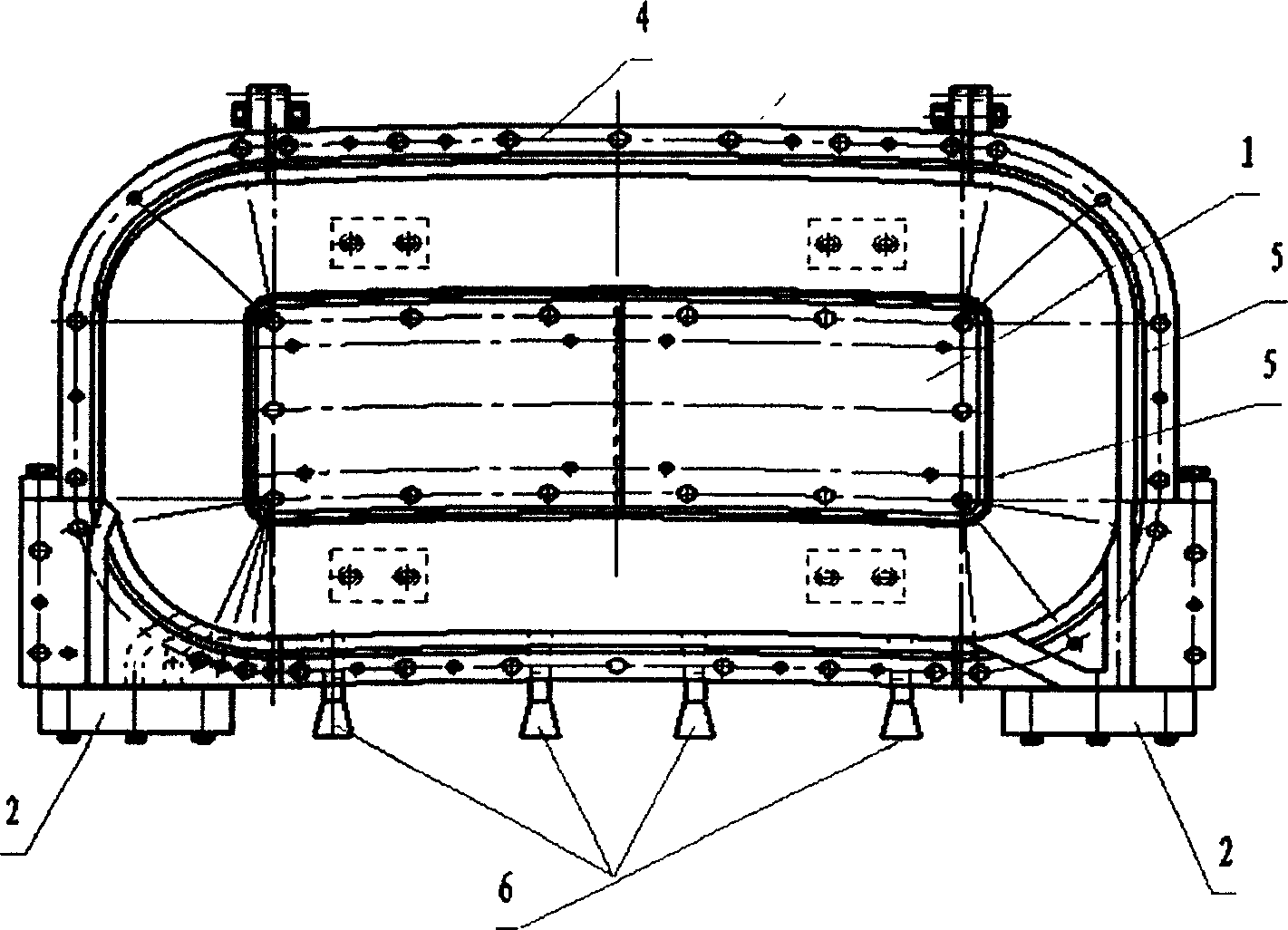
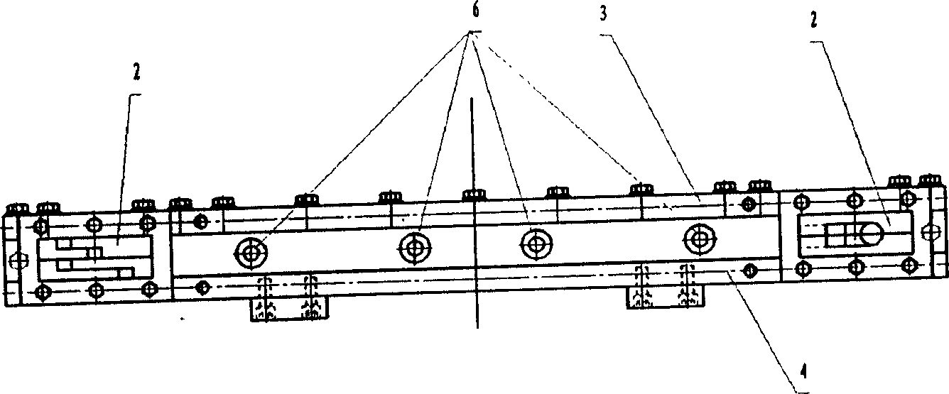
[0063] Such as figure 1 , 2 As shown, it is a schematic diagram of the structure of the epoxy casting mold for the high voltage coil of the electron accelerator, which is composed of the core 1, the gate 2, the upper template 3, the lower template 4, the sealing ring groove 5, the riser 6, and the coil epoxy filling cavity 7.

[0064] The length of the coil is in the range of 0.5-5 meters. According to the requirements of the user, a casting mold of a specification is selected, so that the core 1 is placed in the middle of the upper template 3 and the lower template 4, and the sealing ring groove 5 is placed in the core 1. Around the upper template 3 and the lower template 4, between the core 1 and the sealing ring groove 5 of the upper template 3 and the lower template 4 is the coil epoxy filling cavity 7, and the upper template 3 and the lower template 4 have pouring at both ends. Port 2, 4 risers 6 are placed between the gates 2 at both ends.

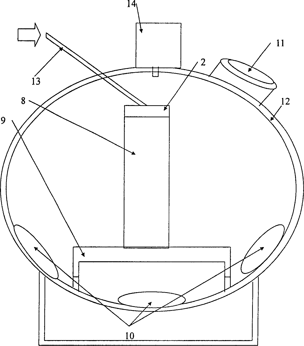
[0065] Such as image 3 Shown is...


PUM


Abstract

The invention relates to a coil epoxy pouring technique. Its feature is that the technique includes the processes like deifilling, putting into vacuum dry room, preheating, vacuumizing, distributing epoxy, mixing glue, irrigating, topping up, solidifying, forming stripping, coil post treatment, etc. And taking the method in the state of definite vacuum extent pours the liquid oxygen in to the mould to a certain temperature and a certain speed to ensure according the technique that the epoxy far away from the casting head freezes first, then freezes towards to the casting head progressively and the freezing of the casting head itself is the last. The feature of the system needed in the technique is that it is made up of coil epoxy pouring mould, vacuum drying room, heater, stirring-bowl, mechanical pump of the stirring-bowl, thermometer, bogie, crane. The advantage of the invention is simple structure, convenience moulding, high insulating strength of the coil, radiation hardening, waterproof, moisture proof, reliable performance, low cost and can adapt for manufacturing.

Description

Technical field [0001] The invention relates to an epoxy pouring process for a high-voltage coil of an electron accelerator, which is used in a beam system of a magnet ring accelerator and belongs to the technical field of coil processing. Background technique [0002] The high voltage coils of electron accelerators currently used in generators are wrapped with mica tape and then heated to form. According to the needs of various users, the length of the coil ranges from 0.5 to 5 meters. Such a large coil depends on this processing technology. It is difficult to guarantee its quality and accuracy, and the surface is easily damaged, the insulation strength is not high, and it is not beautiful. Summary of the invention [0003] The purpose of the present invention is to invent an epoxy pouring process for the high-voltage coil of an electron accelerator that is not easy to damage the surface of the coil, has high insulation strength, high quality and beautiful appearance. [0004] ...

Claims


Application Information

Patent Timeline
IPC IPC(8): H05H7/04
Inventor 邵任杰唐伟康贺鸿生张红辉庄焰王新勇
Owner 上海克林技术开发有限公司
Why Eureka
Try Eureka