Light polarity conversion module and conversion method thereof

A technology of polarity conversion and polarity, which is applied in optics, optical components, nonlinear optics, etc.

Inactive Publication Date: 2005-01-26
示创科技股份有限公司
View PDF0 Cites 3 Cited by
  • Summary
  • Abstract
  • Description
  • Claims
  • Application Information

AI Technical Summary

Problems solved by technology

[0011] The second object of the present invention is to provide an optical polarity conversion module that parallelizes the incident l...

Method used


Image

  • Light polarity conversion module and conversion method thereof
  • Light polarity conversion module and conversion method thereof
  • Light polarity conversion module and conversion method thereof

Examples


Embodiment Construction

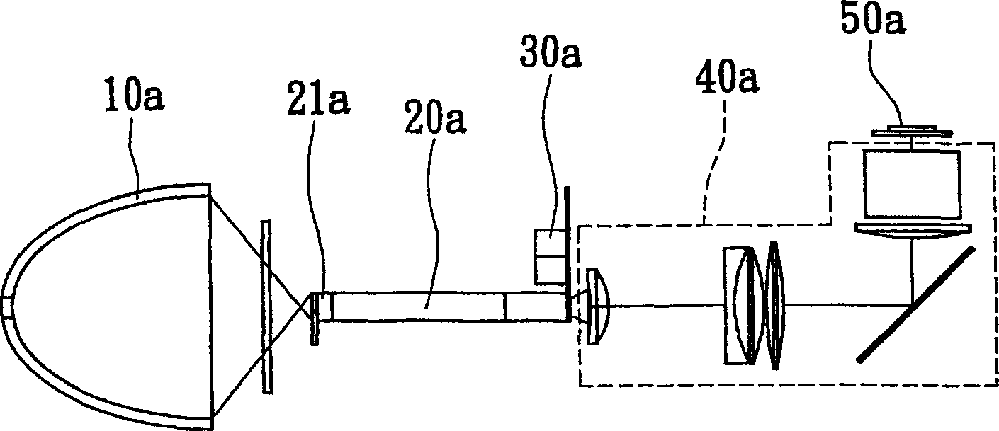
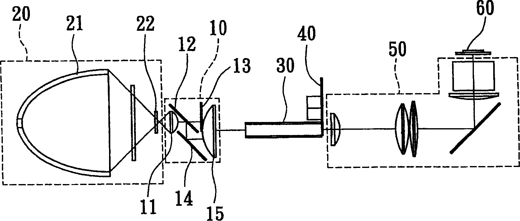
[0050] see image 3 As shown, the present invention provides an optical polarity conversion module 10, which is used in a liquid crystal projection system. The liquid crystal projection system is a single-chip liquid crystal projection system, which includes a light emitting unit 20, an optical polarity conversion module 10, and a uniform light unit. 30. The color transmission wheel 40, the light transmission lens unit 50 and the liquid crystal reflector 60; wherein the light emitting unit 20 includes an ellipsoid lamp 21 and a UV filter 22, so that the ellipsoid lamp 21 emits a light signal and passes through the UV filter The mirror 22 is output to the optical polarity conversion module 10, and the incident optical signal is converted into a single polarity optical signal by the optical polarity conversion module 10, and then focused on the light homogenizing unit 30 to homogenize the optical signal, and passed through The color transmission wheel 40 and the light transmissi...


PUM


Abstract

A photopole conversion module and its method comprises convex lens, polarized light splitter elements, light phase conversion elements, reflecting mirror and condensing lens, which uses convex lens to parallel the incidence light signals and to let some light signals to penetrate polarized light splitter elements and some light is reflected by polarized light splitter and the penetrating light signals are outputted to condensing lens after light phase conversion through light phase conversion elements, and then to use reflecting lens to reflect light signals to the direction of condensing lens which is to focus light signals to an area and to convert the light signal into single polarity in the condition of parallel light to purify the signal and to reduce heat effect with large-size optics elements.

Description

technical field [0001] The invention relates to an optical polarity conversion module, in particular to an optical polarity conversion module of a projection system, that is, a module for converting a luminous signal into a single polarity optical signal. Background technique [0002] Today's liquid crystal projection system is constantly innovating and breaking through technology. It has many advantages such as thin and light weight, no flicker, low radiation, low reflection and better physical plane. It is enough to replace traditional CRT monitors and is accepted by the general public. [0003] see figure 1 As shown, it is a known liquid crystal projection system, which includes an ellipsoid lamp 10a, a cylindrical integrator 20a, a transparent color wheel 30a, a light transmission lens unit 40a, and a reflective liquid crystal panel 50a, wherein the front end of the cylindrical integrator 20a It has an optical polarity conversion unit 21a whose cross-sectional area is t...

Claims


Application Information

Patent Timeline
IPC IPC(8): G02B5/30G02B27/18G02B27/28G02F1/13G03B21/00G03B21/28
Inventor 廖留良
Owner 示创科技股份有限公司
Why Eureka
Try Eureka