
Optical fiber having a lower bending loss

A technology of optical fiber and optical fiber ribbon, applied in the direction of multi-layer core/clad optical fiber, glass optical fiber, clad optical fiber, etc., which can solve the problems of increased transmission loss and other issues

Inactive Publication Date: 2005-02-09
FURUKAWA ELECTRIC CO LTD
View PDF1 Cites 10 Cited by
  • Summary
  • Abstract
  • Description
  • Claims
  • Application Information

AI Technical Summary

Problems solved by technology

A larger increase in transmission loss is noticeable, especially in the L-band (the band between 1565nm and 1625nm), which can exceed 1dB / km, which is where the slot-core fiber optic ribbons that will use certain fibers Problems with cables used for WDM optical transmission over a wide wavelength range

Method used


Image

  • Optical fiber having a lower bending loss
  • Optical fiber having a lower bending loss
  • Optical fiber having a lower bending loss

Examples


Embodiment

[0049] Hereinafter, examples of the present embodiment are described.

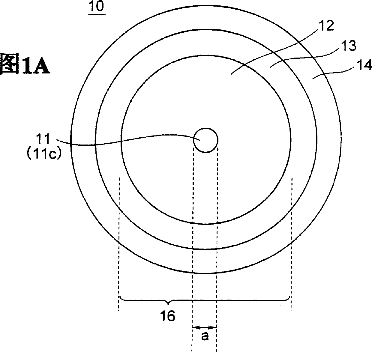
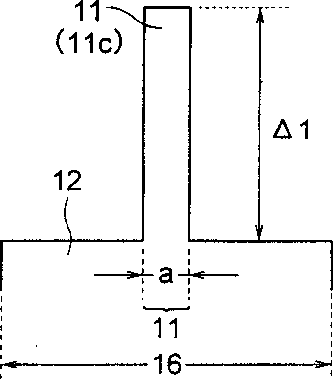
[0050] To produce glass fiber 16 having the refractive index profile shown in the graph of Figure IB, an optical fiber preform is first produced. In the process of manufacturing an optical fiber preform, a porous core powder (soot) including a first core and a partial cladding is formed by vapor axial deposition (VAD). The resulting porous preform is dehydrated and vitrified to obtain a glass core rod.

[0051] It should be pointed out here that in order to be suitable for WDM transmission in the wavelength range of 1285~1625nm, the absorption loss of OH group at 1383nm wavelength needs to be reduced as much as possible, and the Increased absorption loss. Therefore, it is required that OH groups are not mixed into the optical fiber during the manufacturing process.

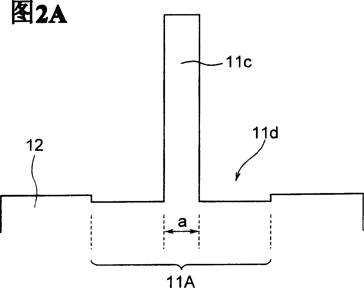
[0052] As mentioned above, the process generally used here is to manufacture the first core 11c and the first core 11c having a diameter a...


PUM

PropertyMeasurementUnit
thicknessaaaaaaaaaa
widthaaaaaaaaaa

Abstract

An optical fiber includes a first core having a relative refractive index difference of larger than 0.36%, and a cladding. The optical fiber has fiber cut-off wavelength lambdac of more than 1350 nm, cable cut-off wavelength lambdacc of less than 1285 nm, bending loss at a wavelength of 1625 nm of not more than 10 dB / km when wound at a diameter of 20 mm, transmission loss at a wavelength range of 1285 to 1625 nm of not more than 0.40 dB / km, transmission loss at a wavelength of 1383 nm less than transmission loss at a wavelength of 1310 nm, and difference in transmission loss at a wavelength of 1383 nm of not more than 0.04 dB / km before and after exposure to hydrogen. The lower bending loss of the optical fiber provides an optical fiber cable for use in a WDM transmission in wavelength range of 1285 to 1625 nm.

Description

technical field [0001] The present invention relates to a low bending loss optical fiber suitable for use in wavelength division multiplexing (WDM) transmission. The present application also relates to an optical fiber cable comprising the optical fiber. Background technique [0002] With the development of optical transmission with higher bit rate and higher capacity, in the field of optical transmission, WDM transmission technology has attracted a lot of attention. In the current WDM transmission field, it is necessary to further increase the transmission capacity, and try to further expand the wavelength range of optical transmission. [0003] It should be pointed out that OH groups may be contained as mixed impurities in conventional optical fibers, and the OH groups have an absorption peak near a wavelength of 1383 nm. Therefore, generally, conventional optical fibers are not suitable for WDM transmission near the wavelength of 1383nm. [0004] In order to solve the ...

Claims


Application Information

Patent Timeline
Patent Type & Authority Applications(China)
IPC IPC(8): C03B37/018C03C13/04C03C25/60G02B6/02G02B6/036G02B6/44
CPCC03C25/607C03C13/047G02B6/02223G02B6/03627G02B6/02266G02B6/03633G02B6/4409G02B6/02014G02B6/02395
Inventor 高桥文雄森平英也渋田妙子
Owner FURUKAWA ELECTRIC CO LTD
Learn More