Tyre mould and its producing method

A technology for tire molds and manufacturing methods, which is applied in the field of molds for manufacturing rubber tires, can solve the problems of low overall mold precision, low finished product pass rate, and long production cycle, and achieves easy control of manufacturing precision, high finished product pass rate, and easy manufacturing process simple effect

Inactive Publication Date: 2005-03-02
象山巨象机模有限公司
View PDF0 Cites 16 Cited by
  • Summary
  • Abstract
  • Description
  • Claims
  • Application Information

AI Technical Summary

Problems solved by technology

[0002] At present, there are roughly three kinds of tire mold manufacturing processes used in my country. One is the gypsum precision casting process, which requires base mold processing, pouring silicone rubber reverse molds, pouring gypsum core molds, plaster mold splicing, and natural drying. , baking, aluminum alloy casting and other processes; the production cycle is long, the o

Method used


Image

  • Tyre mould and its producing method
  • Tyre mould and its producing method
  • Tyre mould and its producing method

Examples


Embodiment 1

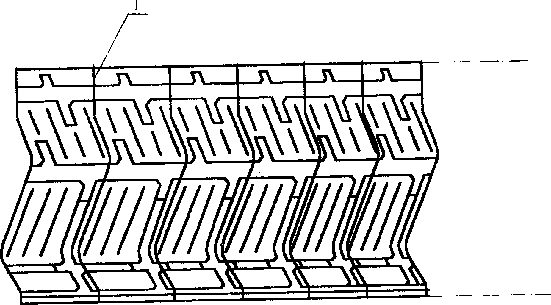
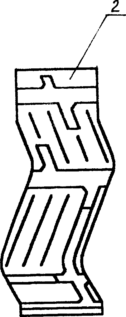
[0020] Step 1. Decompose the P unit: from the attached figure 1 with figure 2 As shown, when the tire tread is unfolded, the tread pattern can be decomposed into several P units. Each P unit 2 has different width dimensions, but the geometric shape is the same. In order to prevent the pattern steel sheet from overlapping with the dividing line, dividing line 1 Divide along the edge of the corolla;

[0021] Step 2, make P unit module: see Figure 5 As shown, the movable mold 6 of the two-half mold module is made according to the tread pattern of the P unit, and the static mold 5 matched with it. After the mold is closed, the cavity 4 is formed. The ejector top plate 7 is set on the movable mold and is made of aluminum alloy. 4 press molding in the cavity;

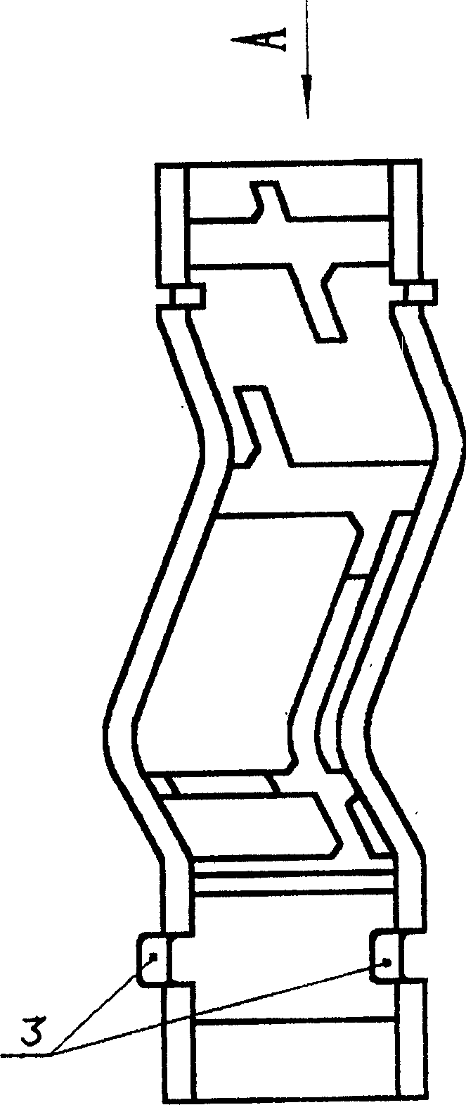
[0022] The made two-half mold P unit module, see image 3 with Figure 4 As shown, the thickness is 25mm, and an angle α is formed along the thickness radial direction. In order to ensure the accuracy of the combined assembly ...

Embodiment 2

[0025] In step 2 of embodiment 1, the material put into the cavity 4 is changed, and the powder metallurgy material is used for extrusion molding in the cavity, and the P unit module is obtained by sintering, and the rest repeats embodiment 1; the P unit module The thickness is controlled between 10-15mm.

Embodiment 3

[0027] Repeat step 1;

[0028] Step 2, make P unit module: see Figure 5 As shown, the movable mold 10 of the active mold module is made according to the tread pattern of the P unit, and the static mold 9 matched with it. After the mold is closed, a cavity 8 is formed. The ejector top plate 11 is set on the movable mold, and the powder metallurgy material is Extrusion molding in the cavity, after sintering, it becomes the P unit module of the active mold;

[0029] The thickness of the active mold P unit module is controlled between 10-15mm, and an angle α is formed along the thickness radial direction. In order to ensure the accuracy of the combined assembly position of the P module, a positioning slot 3 is provided at the end of the P module;

[0030] Step 3. Assembly: see Picture 9 with Picture 10 As shown, there is a segmented mold frame 18 divided into segments ①-⑨. The active mold P unit module 17 produced in step 2 is installed in the segmented mold frame 18 according to th...


PUM

PropertyMeasurementUnit
Thicknessaaaaaaaaaa
Thicknessaaaaaaaaaa

Abstract

The present invention relates to the making process of tyre mold, and is two-half mold and movable for making various tyres, including radial tyre, bias angle tyre, engineering tyre and motorcycle tyre. The present invention features that the tyre mold is modular structure and each tyre mold consists of several tyre mold modules, each of which has one complete tyre pattern. The present invention can simplify the manufacture of tyre mold and the tyre mold has short manufacture period, high precision and high quality.

Description

Technical field [0001] The invention relates to the technical field of molds for manufacturing rubber tires, in particular to a modular manufacturing method including the production of two-half molds and flexible molds for the production of radial car tires, cross-tire tires, engineering tires, and motorcycle tires. Background technique [0002] At present, there are roughly three types of tire mold manufacturing processes used in China. One is the plaster precision casting process, which requires basic mold processing, casting silicone rubber reverse mold, casting plaster core mold, plaster mold splicing, and natural drying. , Baking, aluminum alloy casting molding and other processes; long production cycle, through multiple processes, the overall accuracy of the mold is low, and the finished product qualification rate is low; the second is the electric spark erosion process, which also has the defects of long production cycle and processing cost Too high; the third is the appli...

Claims


Application Information

Patent Timeline
IPC IPC(8): B22F3/10B23P15/24B29C33/38B29D30/08
Inventor 鲍忠林
Owner 象山巨象机模有限公司
Why Eureka
Try Eureka