Low voltage micro liquid drop control device

A technology for controlling devices and micro-droplets, which is applied in the direction of instruments and analytical materials, can solve the problems of unfavorable device miniaturization and high-density integration, large control electrode size, and low droplet moving speed, so as to achieve the driving speed of droplets Fast, small droplet size and low power consumption

Inactive Publication Date: 2005-03-02
TSINGHUA UNIV
View PDF0 Cites 34 Cited by
  • Summary
  • Abstract
  • Description
  • Claims
  • Application Information

AI Technical Summary

Problems solved by technology

[0007] However, there are still some problems in the current microfluidic control technology based on the electrowetting effect on the dielectric material and the microelectrode array: (1) The force generated by the change of the surface tension of the liquid is small, so the droplet moving speed is not high; (2) Since the size of the surface tension of the droplet is inversely proportional to the size of the droplet, this method is not effective when used to control the movement of smaller micro-droplets (such as droplets with a diameter below 10 μm), because the microelectrodes used for control The size is proportional to the size of the droplet to be controlled, so the size of the control electrode required by the current method is too large (in the order of 1mm×1mm), which is not conducive to the miniaturization and high-density integration of the device

Method used


Image

  • Low voltage micro liquid drop control device
  • Low voltage micro liquid drop control device
  • Low voltage micro liquid drop control device

Examples


Embodiment Construction

[0038] The low-voltage micro-droplet control device proposed by the present invention is described in detail in conjunction with the accompanying drawings and embodiments as follows:

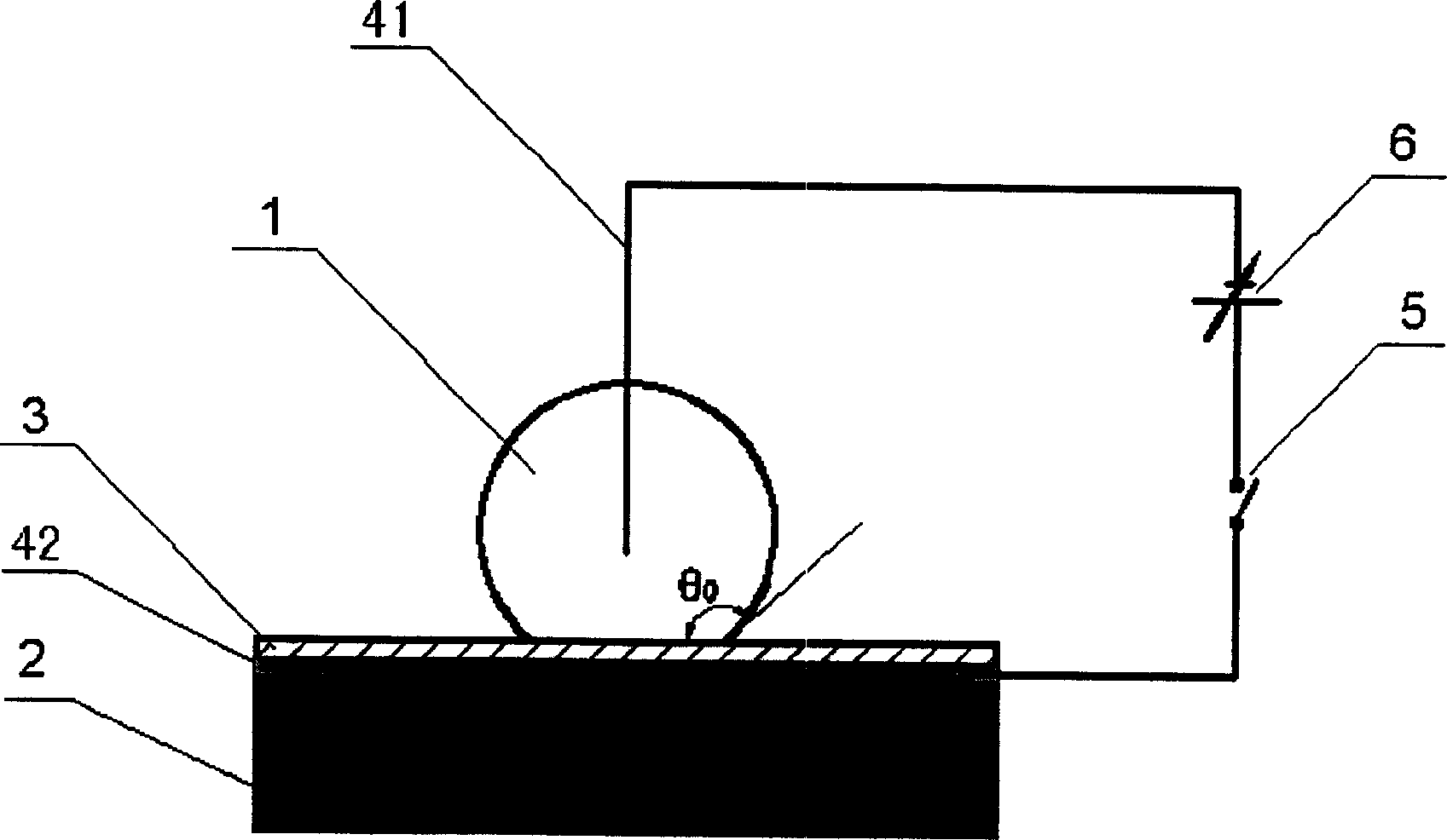
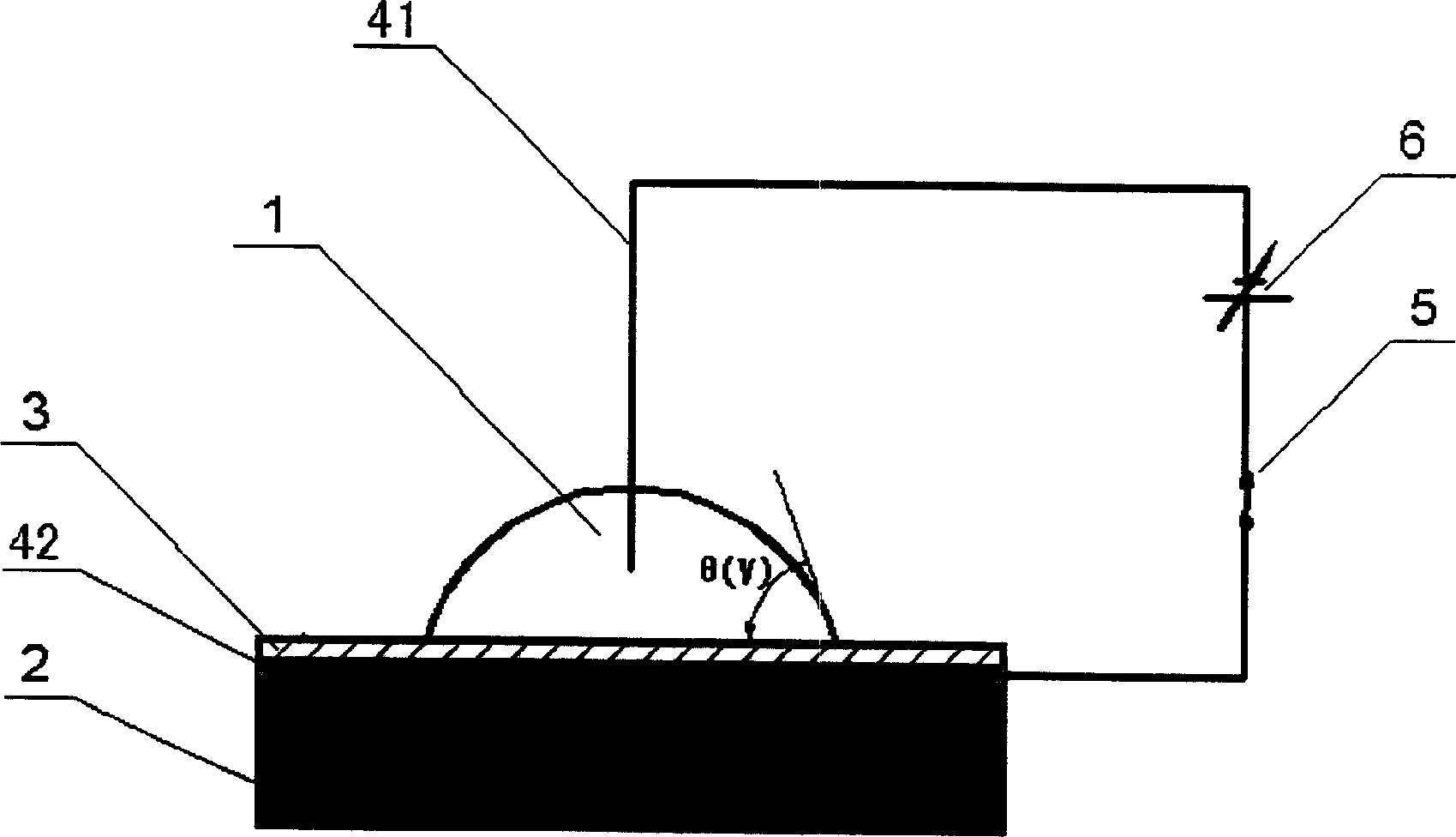
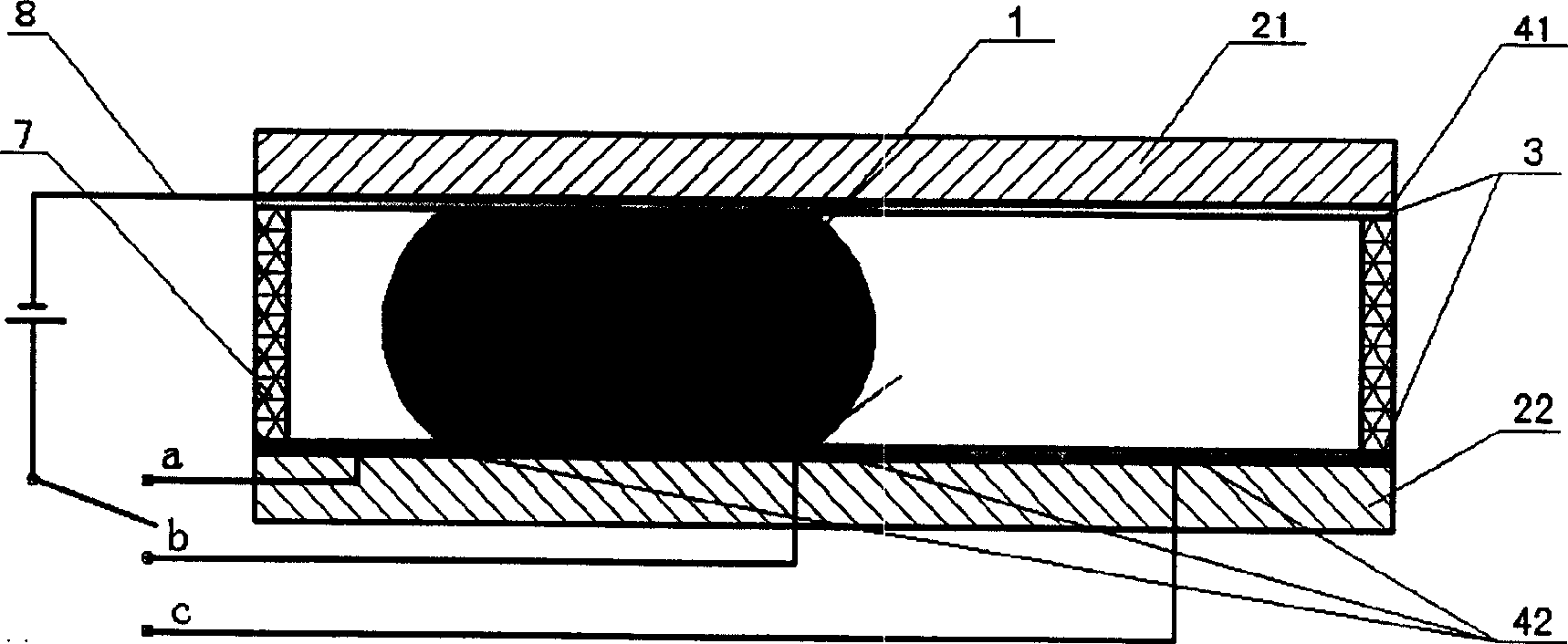
[0039] The structure of a kind of low-voltage droplet control device of the present invention is as follows: image 3 As shown, the device is composed of upper and lower layers of chips and corresponding control circuits. The lower chip is composed of the lower substrate 22 , the control electrode array 42 and the hydrophobic insulating layer 3 , and the upper chip is composed of the upper substrate 21 , the reference electrode layer 41 , the hydrophobic insulating layer 3 and the liquid inlet 9 . The upper and lower chips are mechanically connected by the support structure 7, the reference electrode layer 41 and the control electrode array 42 are electrically connected through the control circuit 8, the reference electrode layer 41 is grounded, and the control electrode array 42 is switched to ...


PUM


Abstract

The invention relates to micro-drop control device with low voltage, which belongs to micro electromechanical technology and microflow control technology fields. The invention includes an upper and a lower layers of chips and correspondent control circuits; the lower chip is made up of a subjacent base board, control circuit array and drain insulating layer; the tow layers of chip is connected mechanically by a supporting structure, the reference electrode layer and the control electrode array are connected by a control circuit, the reference electrode layer is grounded, the circuit electrode array applies positive voltage through a switch; the surface of the lower chip has a micro structure which can enhancing the surface humidity regularly. The invention has all the merits of current device, and the control speed is quick, the consumption is low, and the volume of the device is small.

Description

technical field [0001] The invention belongs to the field of micro-electromechanical system (MEMS) technology and micro-fluid control technology, and in particular relates to the design of a control device for tiny liquid droplets. Background technique [0002] In the past ten years, microfluidic system has gradually developed into a key technology in the field of life sciences, and has a wide range of applications in many fields including biochemistry, medicine, environment, military and industry. [0003] The key and basis for the performance of microfluidic systems is microfluidic control technology, that is, how to manipulate microfluidics quickly, accurately and efficiently. Although there are many microfluidic control technologies at present, there is still a lack of platform technology that combines the advantages of miniaturization, low cost, low power consumption, simplicity and reliability on a sufficiently effective basis, which has also become a constraint for a ...

Claims


Application Information

Patent Timeline
Patent Type & Authority Applications(China)
IPC IPC(8): G01N35/04G01N35/10
Inventor 冯焱颖周兆英叶雄英朱亮
Owner TSINGHUA UNIV
Why Eureka
Try Eureka