Method and apparatus for applying optical fiber array energy source to laser sintering rapid forming

A technology of laser sintering and fiber array, applied in lasers, improving energy efficiency, laser parts and other directions, can solve the problems of low processing efficiency and small processing workpieces, and achieve the effect of low processing cost, small material loss, and improved processing efficiency

Inactive Publication Date: 2005-03-16
ZHONGBEI UNIV
View PDF1 Cites 40 Cited by
  • Summary
  • Abstract
  • Description
  • Claims
  • Application Information

AI Technical Summary

Problems solved by technology

[0005] The purpose of the present invention is to solve the technical difficulties of small workpieces and low processing efficiency existing in the existing laser sintering rapid prototyping technology, and to provide a method and device for laser sintering rapid prototyping of a fiber array energy source with large processing workpieces and high processing efficiency

Method used


Image

  • Method and apparatus for applying optical fiber array energy source to laser sintering rapid forming
  • Method and apparatus for applying optical fiber array energy source to laser sintering rapid forming

Examples


Embodiment Construction

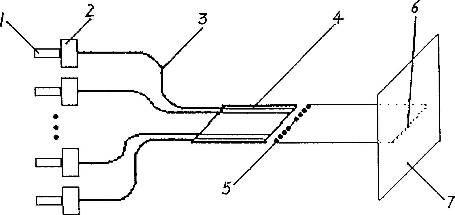
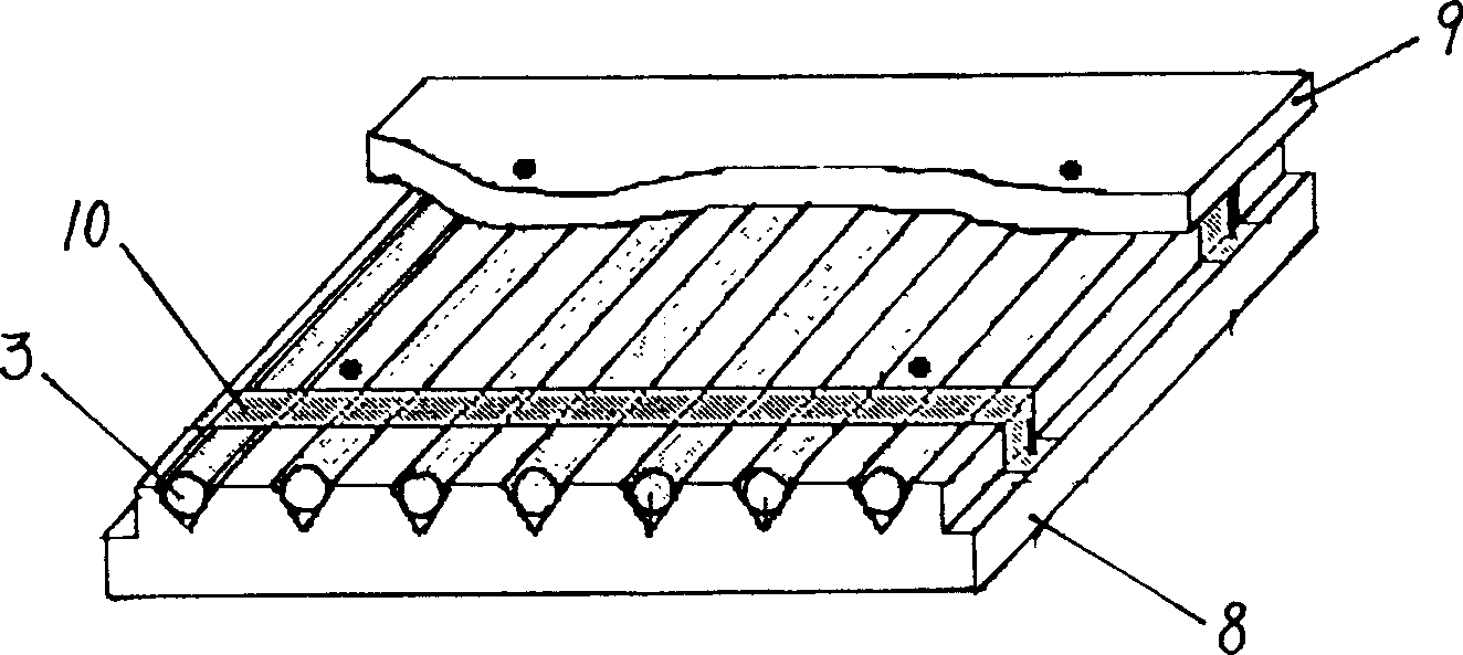
[0016] The optical fiber array energy source in this embodiment is used in the laser sintering rapid prototyping method, which uses several high-power semiconductor lasers (0.5-2W) coupled with optical fibers to form a fiber line array, and then the output of the fiber line array through a microlens array The beams are collimated or converged to form an intermittent laser beam on the working surface; the above two optical fiber arrays are arranged in a symmetrical manner, and two identical intermittent laser beams are outputted in a continuous line after being misaligned in the length direction. The laser beam; the computer is used to control the luminescence of each laser in the fiber line array, and the length and discontinuous position of the continuous laser beam can be changed to realize the laser sintering of complex pattern selection during the scanning process.

[0017] Such as figure 1 As shown, the energy source device for implementing the above method includes several ...


PUM


Abstract

The invention relates to a kind of method of using fibre-optical array energy source for laser firing and quick forming and the device. The invention has not the disadvantages of current laser, such as only being suited to small piece and having low working efficiency. The invention uses a fibre-optical array, which is constituted of several high power semi conduct laser machine and fibre-optical lines, and forms a spiccato laser beam on the work surface with lenticule array. The above two fibre-optical arrays are sited oppositely, and send out two same conterminous laser beams and then form a consecutive beam. Controlling the beam length and the gap place with computer can frit complicated pattern. The invention includes several high power semi conduct laser machine and lenticule array, coupler, miniature model V fibre-optical seat, fibre-optical.

Description

Technical field [0001] The invention relates to a method and a device for using an optical fiber array energy source for laser sintering rapid prototyping. Background technique [0002] Rapid prototyping technology (RPT) can be widely used in machinery, petrochemical, electronics, computers, biomedical engineering, handicrafts and toy manufacturing, including the automotive industry. It can process hard molds and wax molds for precision casting, prototype manufacturing in new product development and design modification, and can also be used on complex parts that are difficult to machine and some single-piece functional or structural parts. [0003] At present, the main equipment and process methods for rapid prototyping in the world are as follows: three-dimensional printing method (SLA, also called photosensitive resin curing), selective laser sintering method (SLS), layered entity method (LOM, also called paper cutting) Method) and selective spraying method (FDM). The three-dim...

Claims


Application Information

Patent Timeline
Patent Type & Authority Applications(China)
IPC IPC(8): B22F3/105B29C67/04H01S3/00H01S3/067
CPCY02P10/25
Inventor 朱林泉王高周汉昌
Owner ZHONGBEI UNIV
Why Eureka
Try Eureka