

Polarizing plate and liquid crystal display device using the same
A technology of polarizing plate and polarizing element, applied in the field of polarizing plate, can solve the problems of large thermal expansion coefficient, dimensional change, small specific gravity of substrate, etc.
- Summary
- Abstract
- Description
- Claims
- Application Information
AI Technical Summary
Problems solved by technology
Method used
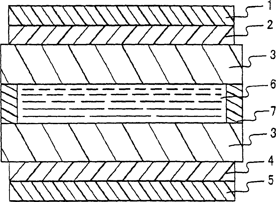
Image

Examples
Embodiment 1
[0066] Dissolve the PVA powder with an average degree of polymerization of 1700 and an average degree of saponification of 97.0% moles in pure water, adjust it to a 10% by mass aqueous solution, apply this aqueous solution to a polyester film, and dry it at 50°C for 2 hours, then dry it at 130°C. ℃ for 30 minutes to obtain a PVA film with a thickness of 40 μm. The obtained film was swollen under warm water at 30° C. for 1 minute, and then immersed in an aqueous solution of potassium iodide / iodine (mass ratio 10:1) at 30° C. to extend to 2 times. Next, in a 4% by mass boric acid solution at 50°C, the total elongation was tripled, then immersed in water at 30°C, washed, and dried at 50°C for 4 minutes to obtain a polarizing element with a thickness of 13 μm. The concentration of the aqueous solution of potassium iodide / iodine (mass ratio 10:1) ensured that the iodine concentration was 0.35% by mass so that the transmittance of the polarizing element became 44%.
Embodiment 2
[0068] Dissolve the PVA powder with an average degree of polymerization of 1700 and an average degree of saponification of 97.0% moles in pure water, adjust it to a 10% by mass aqueous solution, apply this aqueous solution to a polyester film, and dry it at 50°C for 2 hours, then dry it at 130°C. ℃ for 30 minutes to obtain a PVA film with a thickness of 50 μm. The obtained film was swollen under warm water at 30° C. for 1 minute, and then immersed in an aqueous solution of potassium iodide / iodine (mass ratio 10:1) at 30° C. to extend to 2 times. Next, in a 4% by mass boric acid solution at 50° C. to achieve a total elongation of 3 times, then immersed in water at 30° C., washed, and dried at 50° C. for 4 minutes to obtain a polarizing element with a thickness of 18 μm. The concentration of the aqueous solution of potassium iodide / iodine (mass ratio 10:1) ensured that the iodine concentration was 0.33% by mass so that the transmittance of the polarizing element became 44%.
Embodiment 3
[0070] The film with a thickness of 40 μm obtained in Example 1 was swelled in warm water at 30° C. for 1 minute, then immersed in an aqueous solution of potassium iodide / iodine (mass ratio 10:1) at 30° C., and extended to 3 times. Next, in a 4% by mass boric acid solution at 50° C. to achieve a total elongation of 5.5 times, then immersed in water at 30° C., washed, and dried at 50° C. for 4 minutes to obtain a polarizing element with a thickness of 9 μm. The concentration of the aqueous solution of potassium iodide / iodine (mass ratio 10:1) ensured that the iodine concentration was 0.37% by mass so that the transmittance of the polarizing element became 44%.
PUM
| Property | Measurement | Unit |
|---|---|---|
| thickness | aaaaa | aaaaa |
| thickness | aaaaa | aaaaa |
| thickness | aaaaa | aaaaa |
Abstract
Description
Claims
Application Information