Slewing ring

A technology for slewing rings and outer rings, applied in the field of slewing rings, can solve the problems of weakened characteristics, reduced lubricant pollution, and reduced ring life, etc., to achieve the effects of reduced risk of rupture, increased time delay, and reduced wear

Active Publication Date: 2005-03-23
DEFONTAINE
View PDF3 Cites 4 Cited by
  • Summary
  • Abstract
  • Description
  • Claims
  • Application Information

AI Technical Summary

Problems solved by technology

[0003] The main disadvantage of this type of ring is that during rotation the cage comes into contact with the ring and wears out due to the resulting friction
This wear leads firstly to contamination of the lubricant, which weakens its properties, and secondly to a reduction in the life of the rings
[0004] A solution to this problem has been proposed: the surface of the ring is thermally and / or chemically treated (eg US2001 / 48781 or EP0531082) where it is in contact with the cage, since this treatment cannot be applied to the It is very difficult to implement the diameter of the ring; or set a porous part containing lubricant on the cage (such as GB1396220 and JP10089365), but the manufacture of the cage is very complicated
[0005] Therefore, the problem posed is to obtain a slewing ring whose contamination by lubricant is greatly reduced and the life of the ring is greatly increased

Method used


Image

  • Slewing ring

Examples


Embodiment Construction

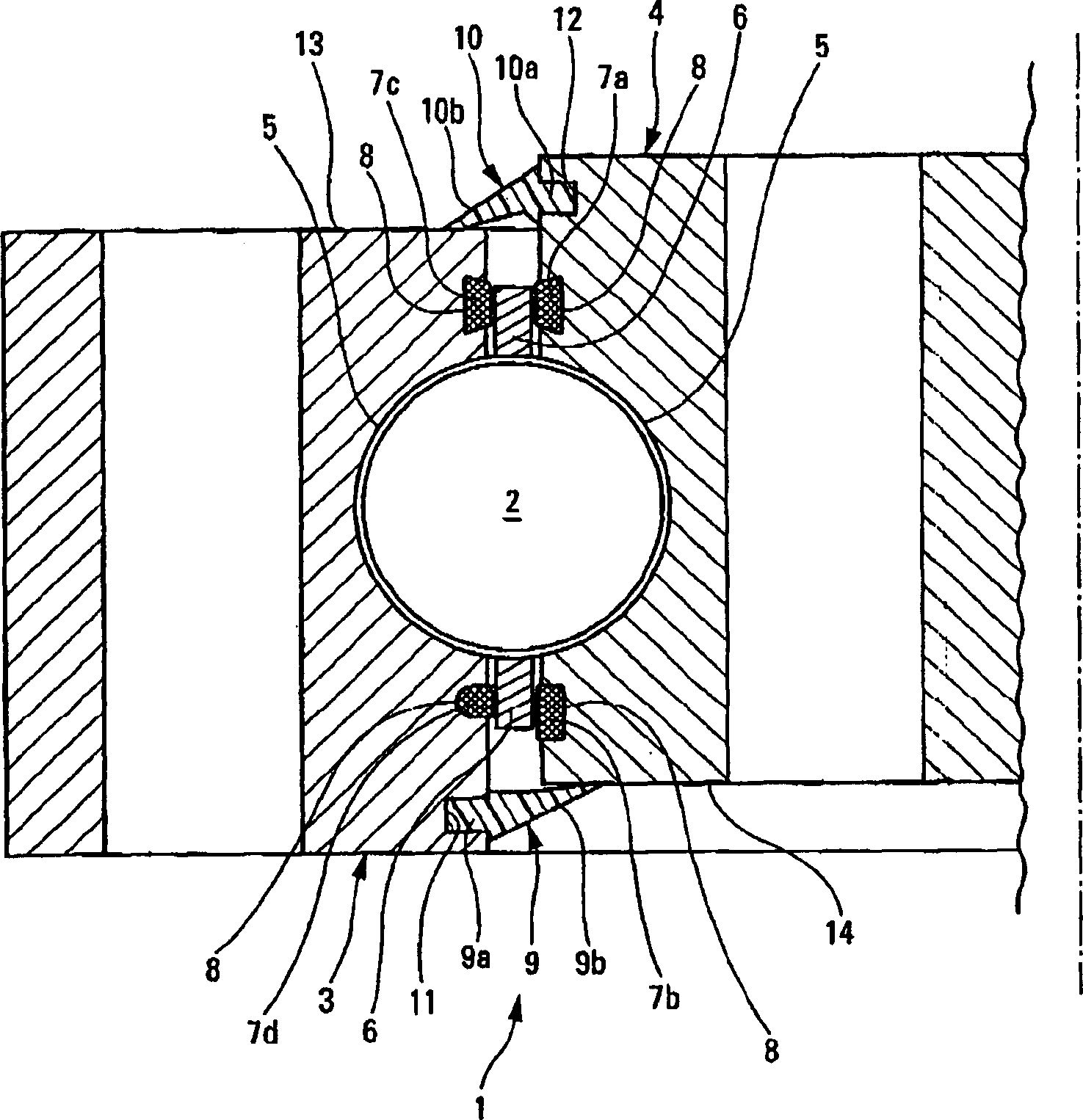
[0008] Further details and advantages of the invention emerge from the following detailed description of specific embodiments, which are non-limiting and illustrative, in conjunction with the accompanying drawings.

[0009] As shown in the figure, the slewing ring 1 comprises in a known manner:

[0010] Rolling member 2 (in this embodiment, ball member 2);

[0011] two concentric rings 3, 4 (one inner ring 3 and one outer ring 4) of steel, which rotate relative to each other, form the raceway 5 of the ball part 2, and

[0012] A steel cage 6 arranged between the two concentric rings 3, 4 extends in the axial direction of the slewing ring 1 on one side of the ball part 2, the cage rotates integrally with the ball part, and the The cage holds the rolling elements at regular intervals in the raceway.

[0013] Also, the slewing ring 1 comprises contact parts, also called contact rings 7a, 7b, 7c, 7d, made of a non-ferrous metal material, in this embodiment polyamide, for example...


PUM


Abstract

The radial bearing (1) consists of outer (3) and inner (4) metal rings with races (5) for rolling bodies (2) such as balls or rollers in a metal cage (6) with a hardness similar to that of the rings. - The radial bearing (1) consists of outer (3) and inner (4) metal rings with races (5) for rolling bodies (2) such as balls or rollers in a metal cage (6) with a hardness similar to that of the rings. It also has at least one circular contact ring (7a, 7b, 7c, 7d) made from a material with a different hardness to the bearing rings and cage, set in one or more grooves (8) in the bearing rings and preventing any direct contact vbetween the cage and bearing ring(s) with the groove(s). The contact rings can be made from a non-ferrous metal such as a copper alloy or bronze, or from a polymer material.

Description

technical field [0001] The present invention relates to a slewing ring, in particular to a ball bearing. Background technique [0002] A known type of slewing ring comprising rolling elements, two concentric metal rings of given hardness, an inner ring and an outer ring, rotating relative to each other and defining a raceway for said rolling elements, one made of metal . A cage having substantially the same hardness as the rings, said cage being disposed between two rings and rotating integrally with the rolling elements, said cage holding said rolling elements in said raceways at regular intervals . [0003] The main disadvantage of this type of ring is that during rotation the cage comes into contact with the ring and wears out due to the resulting friction. This wear leads firstly to contamination of the lubricant, which weakens its properties, and secondly to a reduction in the life of the rings. [0004] A solution to this problem has been proposed: the surface of th...

Claims


Application Information

Patent Timeline
Patent Type & Authority Applications(China)
IPC IPC(8): F16C33/66F16C17/02F16C17/10F16C33/38F16C33/44F16C33/62F16C33/64F16C33/78
CPCF16C33/78F16C17/10F16C2300/14F16C33/3856F16C33/583F16C17/02F16C33/44F16C33/3806F16C19/16F16C21/00F16C33/385F16C33/543F16C2360/31F16C33/76F16C2208/60
Inventor 迪迪耶·沙特里达尼埃尔·泰尔弗
Owner DEFONTAINE
Why Eureka
Try Eureka