Magnetic suspension device of float capable of random two-way automatic rotation and its control system

An automatic rotation and control system technology, applied in the direction of the magnetic attraction or thrust holding device, display device, instrument, etc., can solve the problems of single direction of automatic rotation, inconvenient use, troublesome, etc., to achieve expanded functions and uses, Simple structure and circuit, easy to manufacture

Inactive Publication Date: 2005-03-23
NINGBO TIANMING ELECTRONICS
View PDF0 Cites 30 Cited by
  • Summary
  • Abstract
  • Description
  • Claims
  • Application Information

AI Technical Summary

Problems solved by technology

[0002] Among the many existing magnetic levitation devices, the floating body either has no automatic rotation function or has an automatic rotation function, but its permanent automatic rotation rotation direction, once the relevant structure and circuit are set, its automatic rotation direction is single , if reversed manually, it will stop rotating or rotate in the original direction after a while
Therefore, the rotation direction of the floating body is monotonous, which is inconvenient to use, and if you want to adjust the automatic rotation direction of the floating body, you need to adjust the relevant structure and circuit, which is also very troublesome

Method used


Image

  • Magnetic suspension device of float capable of random two-way automatic rotation and its control system
  • Magnetic suspension device of float capable of random two-way automatic rotation and its control system
  • Magnetic suspension device of float capable of random two-way automatic rotation and its control system

Examples


Embodiment 1

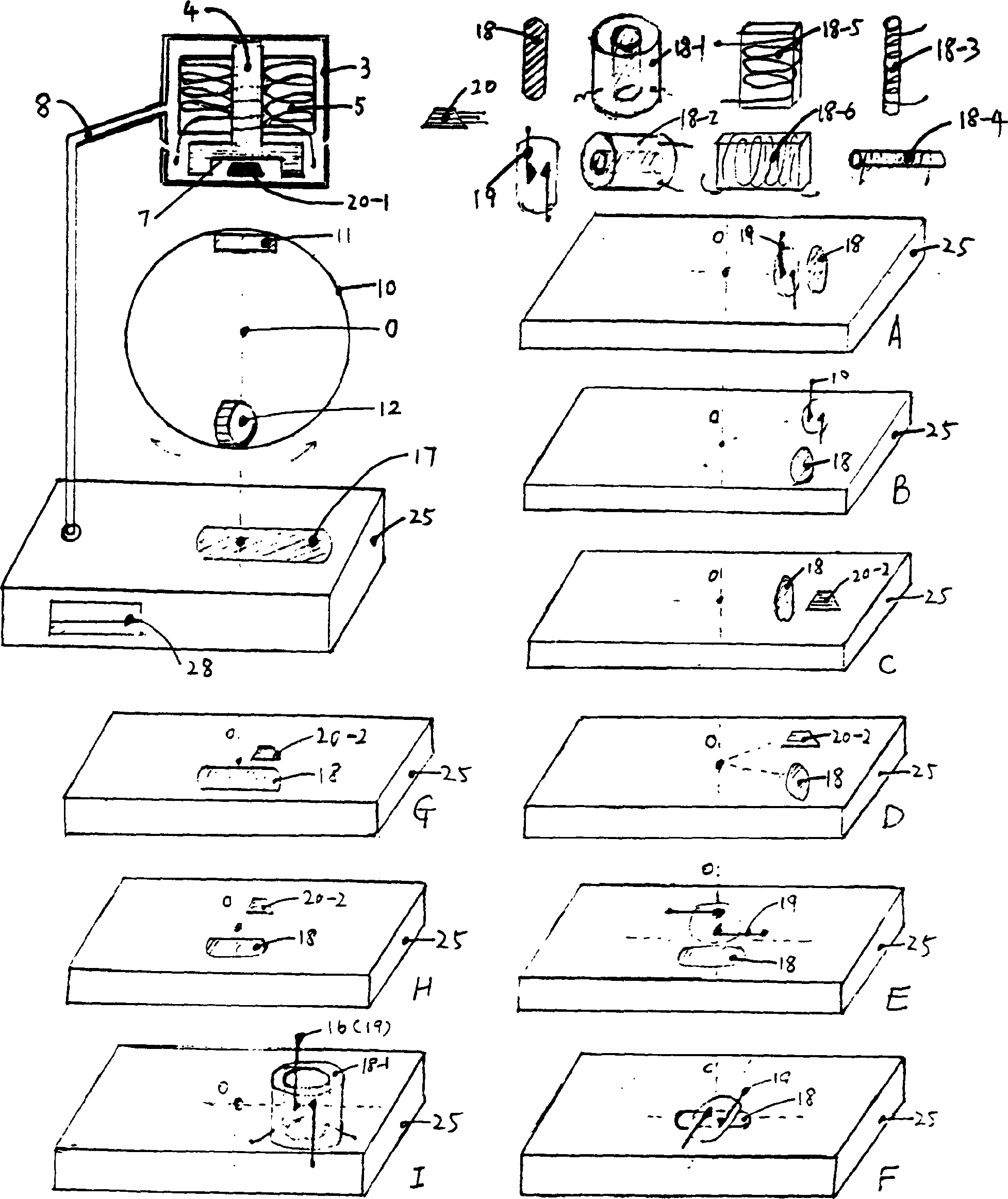
[0042] Embodiment 1 (as attached figure 1 shown), wherein the electromagnet 2 is arranged on the upper part of the frame box 1, which is composed of the iron core 4 and the coil 5 of the outer cover thereof, at the plane layer of the lower side of the iron core 4 or in the shape of the lower side of the iron core 4 A horizontal displacement sensor 6 is arranged in the cavity groove 7 of the upper concave iron core, which adopts a magnetic sensitive diode or a magnetic sensitive triode or a magnetic sensitive resistor, or a magnetic induction linear Hall element or a magnetic induction linear Hall sensor integrated circuit element 20 -1.

[0043] The center of gravity vertical line 0 position of the upper part in the globe 10-1 is provided with the magnetic levitation permanent magnet 11 that the magnetic levitation permanent magnet 11 that produces different magnetic polarity with the electromagnet that lays flatly, and the position along the center gravity center vertical lin...

Embodiment 2

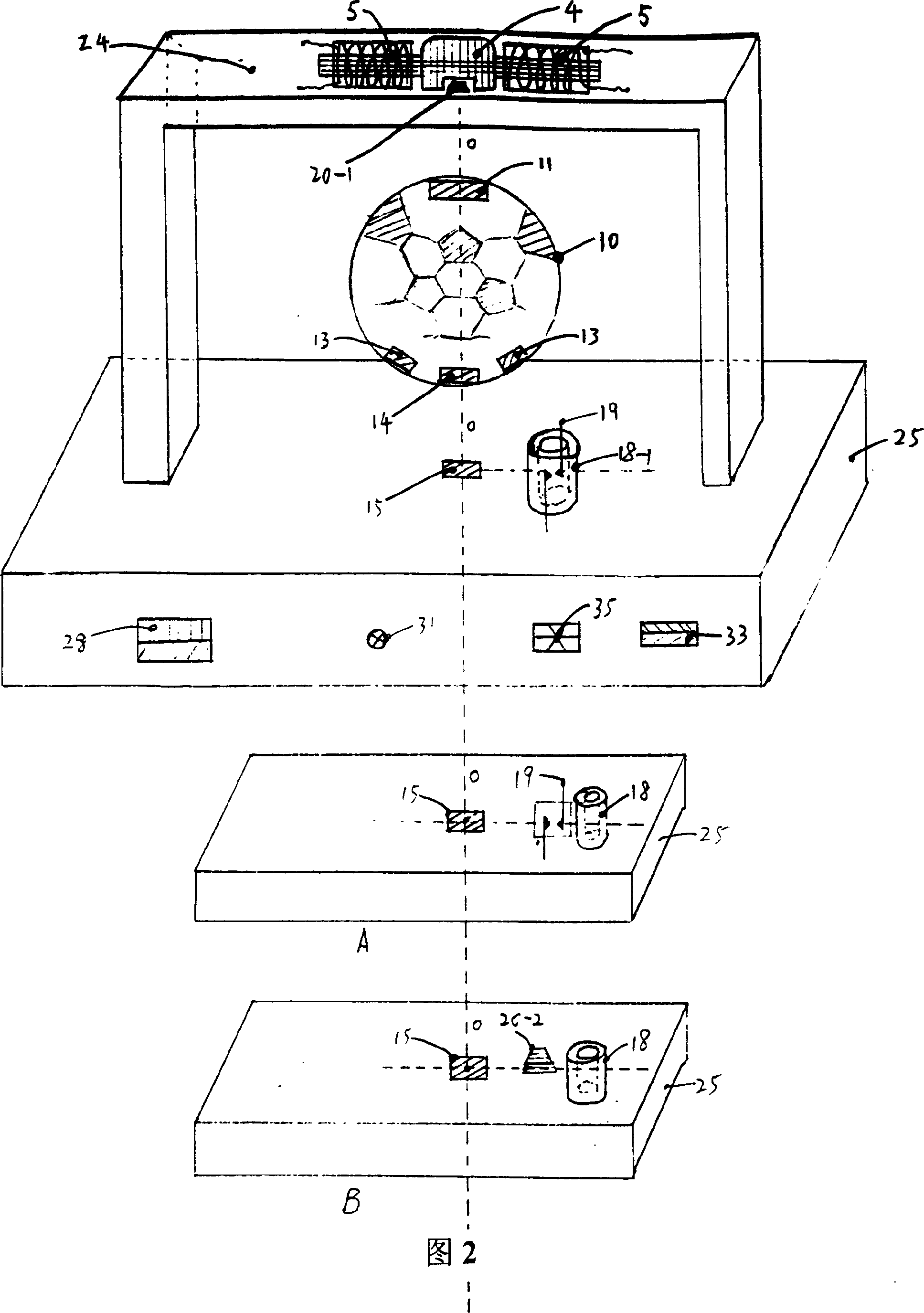
[0051] Embodiment 2 (as shown in Figure 2) is a kind of upper beam that presents football goal frame model 24 as a whole, and floating body 10 is football model 10-2, and electromagnet 2 adopts horizontal double arm electromagnet, and iron core 4 middle parts are equipped with The downward magnetic head and its left and right sides each have a horizontally placed iron core 4 covered with an electromagnet coil 5. When the two electromagnet coils 5 are energized, the electromagnetic fields generated by them are opposite and pass through the magnetic head. A superimposed electromagnetic field is emitted from below, which generates different magnetic polarities on the upper side of the magnetic levitation permanent magnet 11 placed flat on the upper end of the football model 10-2 below and attracts each other, and the football model 10-2 is sucked upwards to cope with the football model. 10-2 Due to the force of falling due to its own weight, the lower end of the magnetic guide hea...

Embodiment 3

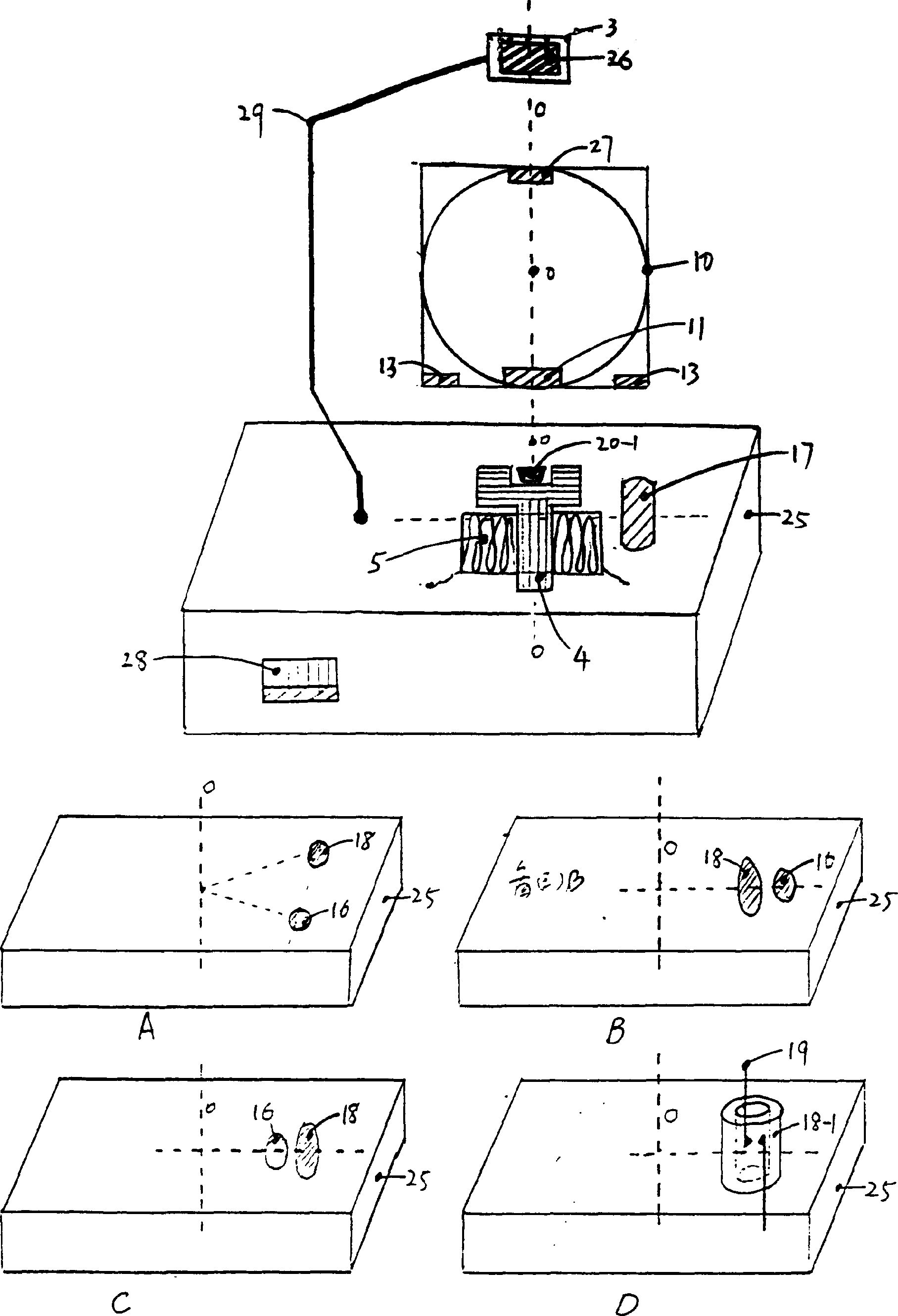
[0054] Embodiment 3 (as image 3shown), the electromagnetic box 3 of a flat permanent magnet 26 is built-in at the top of the upper end of the frame box 1, and it is supported by a support 29 that can be a solid core body. The upper end of each type of floating body 10 is equipped with a flat permanent magnet 27, which attracts with the permanent magnet 26 above with different magnetic polarities to form an upward pull force on the floating body 10, and the lower part of the floating body 10 is along the center of gravity vertical line 0 A maglev permanent magnet 11 is installed at the place, and at least one flat rotating permanent magnet 13 is installed on its side. In the lower base box 25 of the lower frame box body 1 of the buoyant body 10, an iron magnet is housed at the center of gravity vertical line 0 position. The electromagnet 2 with the opening of the core 4 turned upside down, when the coil 5 of the electromagnet 2 is energized, it sends an electromagnetic field u...


PUM


Abstract

A floating body can be as the magnetic levitation system of the bidirectional random autorotation and its control system. It is are composed of the magnetic levitation permanent magnet embedded in the floating body, electromagnet in the trestle cabinet, displacement transducer, magnetic levitation control circuit, rotary permanent magnet embedded in the floating body, magnetic magnet coil in the trestle cabinet, proximity transducer and rotary control circuit respectively. It is featured by the convenient use. On the corresponding magnetic levitation system, it can evolve into the magnetic levitation tellurions, spheres, balls, toys, advertising products, model exhibitions, souvenirs, artwares.

Description

Technical field: [0001] The invention relates to a magnetic levitation device, in particular to a magnetic levitation device with bidirectional random automatic rotation of a floating body and a control system thereof. Background technique: [0002] Among the many existing magnetic levitation devices, the floating body either has no automatic rotation function or has an automatic rotation function, but its permanent automatic rotation rotation direction, once the relevant structure and circuit are set, its automatic rotation direction is single , if reversed manually, it will stop rotating or rotate in the original direction after a while. Therefore, the rotation direction of the floating body is monotonous, which is inconvenient to use, and in order to adjust the automatic rotation direction of the floating body, it is necessary to adjust related structures and circuits, which is also very troublesome. Invention content: [0003] Aiming at the above-mentioned deficiencie...

Claims


Application Information

Patent Timeline
Patent Type & Authority Applications(China)
IPC IPC(8): G09B29/00G09F19/00H02N15/00
Inventor 唐建一
Owner NINGBO TIANMING ELECTRONICS
Why Eureka
Try Eureka