
Method of enhancing phase shift masks

A phase-shift mask and mask technology, applied in the field of integrated circuits and their manufacturing, can solve the problems of manufacturing window limitation, complex patterning of binary masks, etc.

Inactive Publication Date: 2005-03-30
ADVANCED MICRO DEVICES INC
View PDF3 Cites 0 Cited by
  • Summary
  • Abstract
  • Description
  • Claims
  • Application Information

AI Technical Summary

Problems solved by technology

As such, the patterning of the binary mask may become complex and the fabrication window of this technology may be limited

Method used


Image

  • Method of enhancing phase shift masks
  • Method of enhancing phase shift masks
  • Method of enhancing phase shift masks

Examples


Embodiment Construction

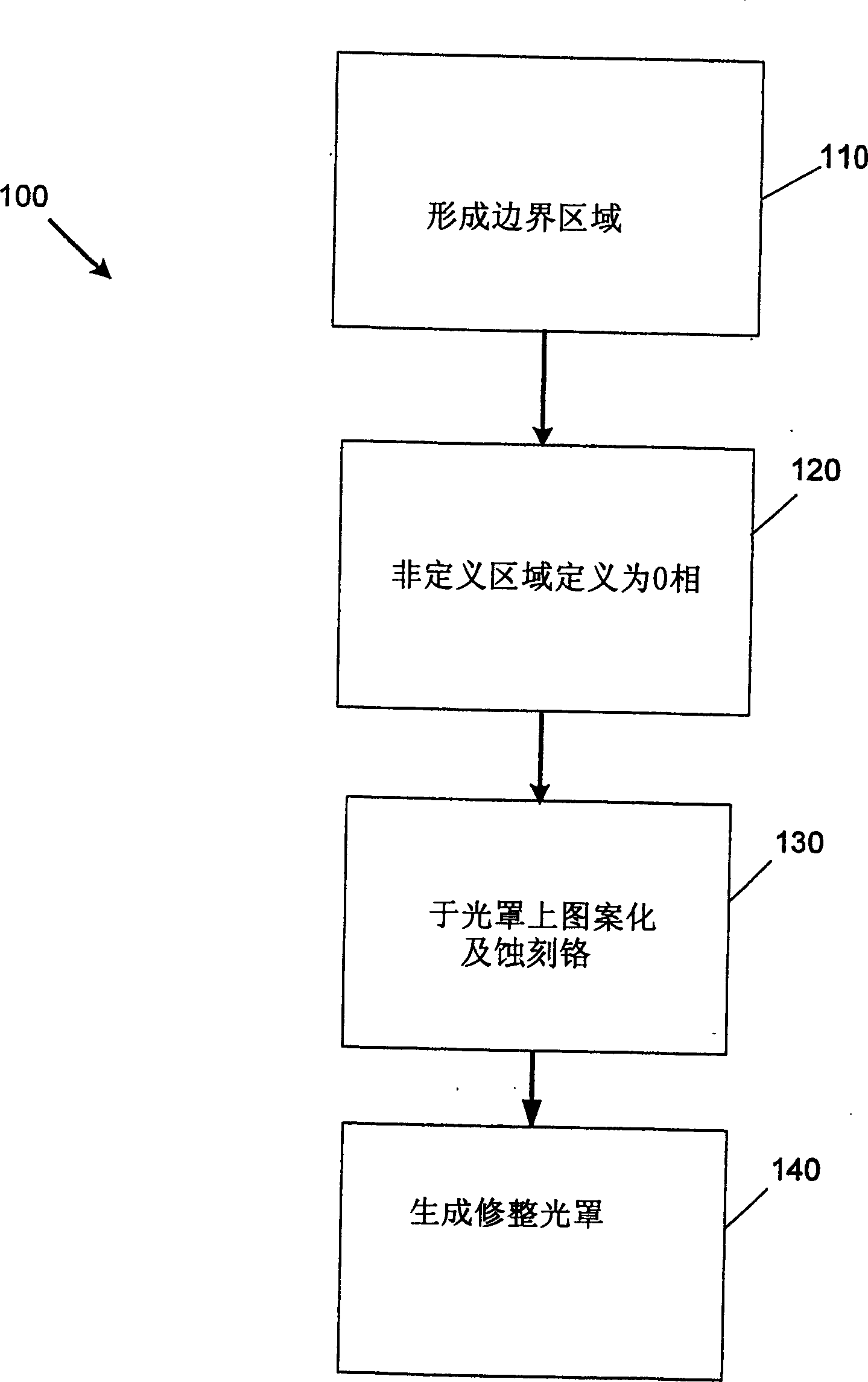
[0028] FIG. 1 shows a flowchart 100 illustrating exemplary steps in the composition or design of a phase shift mask (PSM) and an electric field or trim mask. A set of previously defined 0-phase or 180-phase regions on the phase mask will help identify a critical polymorphic region. The 0-phase or 180-phase regions can be generated by hand, using currently available software programs, or creating an optimal program to define the regions.

[0029] In step 110, a chrome boundary region (chrome boundary region) is formed outside the 180 phase region edge of the 180 phase region previously defined by the phase mask, and the 180 phase region does not define a final polycrystalline pattern (final poly pattern) ). The non-transparent border region can be defined either by hand or using a computer software program. Characteristically, the design database generated by merging the defined non-transparent border regions with critical level patterns can be used for "die-to-database" veri...


PUM


Abstract

A mask generation method can enhance clear field phase shift masks using a chrome border around phase 180 regions. An exemplary method involves identifying edges of a 180 degree phase pattern, expanding these edges, and merging the expansions with chrome. An alternative method involves oversizing and undersizing phase 180 data, taking the difference, and merging the difference with chrome. The chrome region on the phase mask can improve mask generation by allowing the chrome on the mask to fully define the quartz etch.

Description

technical field [0001] The present invention relates to integrated circuits and methods of fabrication thereof, and more particularly to generating phase-shifted patterns to improve patterning of gates and other layers, structures, or regions requiring sub-nominal dimensions. Background technique [0002] Semiconductor devices or integrated circuits may contain millions of components such as transistors. Very large integrated (ULSI) circuits may include complementary metal oxide semiconductor (CMOS) field effect transistors (FETs). Despite existing system capabilities and manufacturing processes for millions of IC components on an IC, there is still a need to reduce the feature size of the IC components, thereby increasing the number of components on an IC. [0003] One limitation in achieving downsizing of IC devices is existing lithography capabilities. Lithography The process by which patterns or images are transferred from one medium to another. Existing IC lithograph...

Claims


Application Information

Patent Timeline
Patent Type & Authority Applications(China)
IPC IPC(8): G03F1/26G03F1/00G03F1/30G03F1/68H01L21/027
CPCG03F1/144G03F1/30G03F1/70G03F1/26G03F1/68
Inventor T·P·卢康科C·A·斯彭斯
Owner ADVANCED MICRO DEVICES INC
Learn More