Eureka AIR delivers breakthrough ideas for toughest innovation challenges, trusted by R&D personnel around the world.

Ultra-high power supersonic generator sharing a oscillation source

A super-power, generator technology, applied in the direction of the fluid using vibration, can solve the problems of inconvenient operation, the ultrasonic generator cannot reach the best working state, the transformer is bulky, etc.

Inactive Publication Date: 2005-07-06
杜鹏 +1
View PDF0 Cites 9 Cited by
  • Summary
  • Abstract
  • Description
  • Claims
  • Application Information

AI Technical Summary

Problems solved by technology

[0005] The technical inadequacy of existing ultrasonic generation is that the output frequency of the signal generator cannot be selected arbitrarily, and the frequency range is only in the range of 16KHz-120KHz at most.
One signal generator can only drive a homologous power amplifier of 5KW at most. If it is necessary to produce an ultrasonic generator above 40KW, it needs to use multiple signal generators to complete, and the same frequency point and synchronization of these multiple signal generators Difficult to solve, the ultrasonic generator will not work optimally
[0006] For the power adjustment of the ultrasonic generator, if the transformer is used to adjust the output voltage, it can also be used for low-power (<1KW) ultrasonic generators, but it will not work for high-power or super-high-power ultrasonic generators, because the transformer used Not only bulky, but also expensive and inconvenient to operate
If the power adjustment adopts the inductance of the matching network, it is also not suitable for high-power and ultra-high-power ultrasonic generators, because the result of using this method will increase the internal friction of the generator and reduce the conversion efficiency of power output.

Method used


Image

  • Ultra-high power supersonic generator sharing a oscillation source
  • Ultra-high power supersonic generator sharing a oscillation source
  • Ultra-high power supersonic generator sharing a oscillation source

Examples


Embodiment Construction

[0021] Selected ultrasonic frequency: 28KHz

[0022] Ultrasonic power: 1.2KW

[0023] The model structure is a split structure of the metal melting tank. Among them, the main device parameters in each circuit diagram are selected as follows:

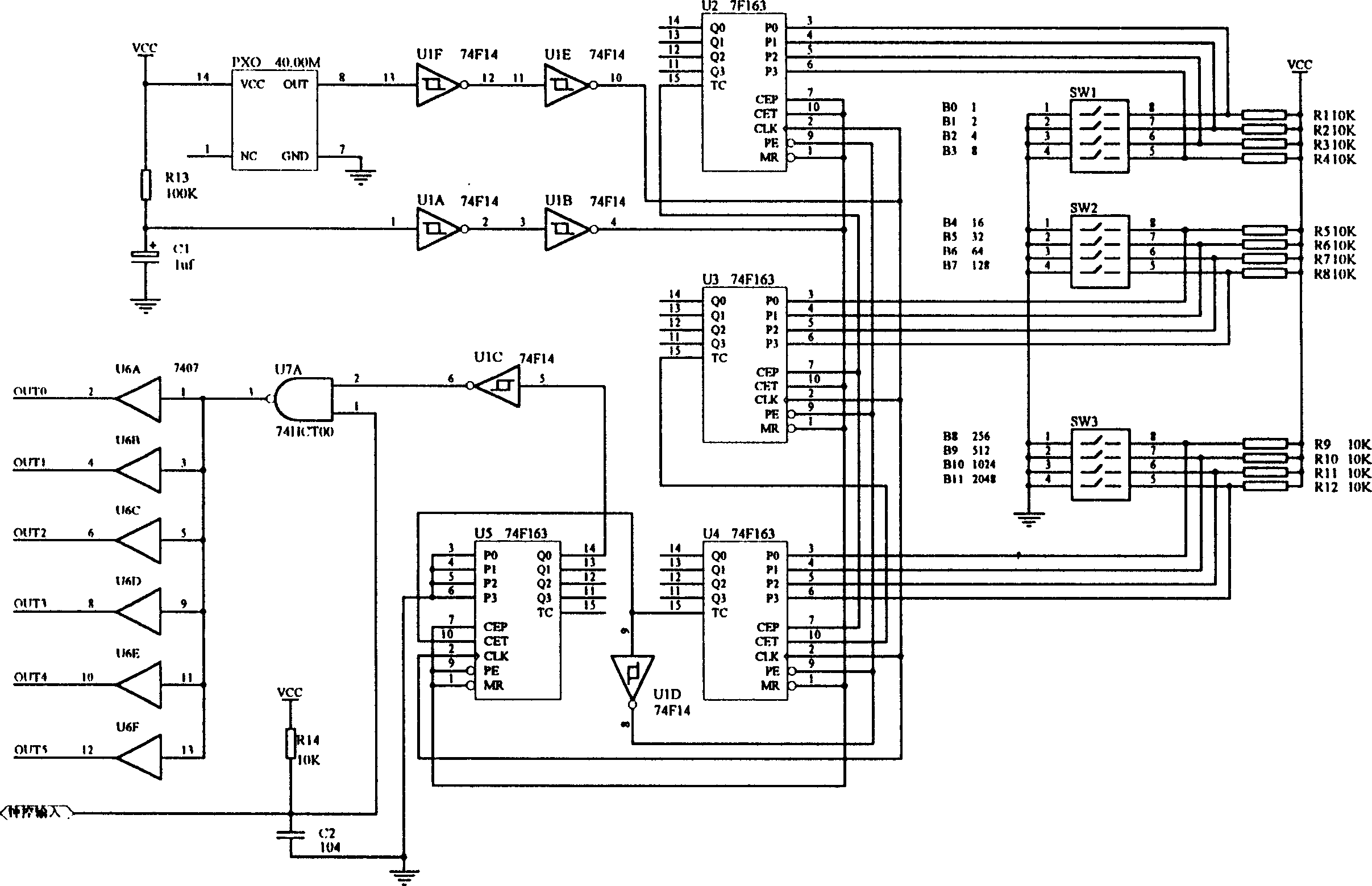
[0024] 74F14—Six reverse Schmitt triggers

[0025] 74FCT00—Quad 2-Input NAND Gate

[0026] 7407—hex buffer / driver

[0027] 74F163—4-bit binary counter

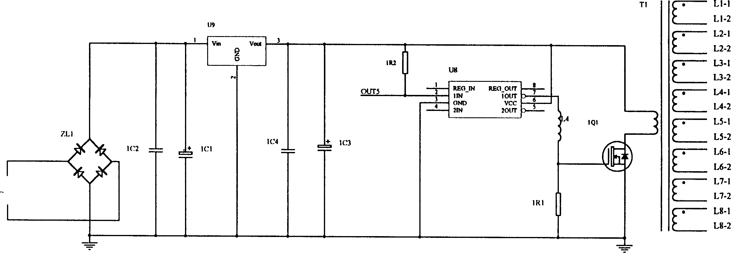
[0028] CPS2811—Two-input and two-output driver

[0029] FR107—fast recovery diode produced by Fairchild, USA

[0030] SSH7N90A—Field effect tube produced by Fairchild, USA

[0031] The quartz crystal oscillator is 40MHz

[0032] KBPC2506 silicon rectifier bridge stack

[0033] 25A600V made in Taiwan

[0034] In the 15KHz-2MHz wide-range frequency source, the method of selecting any frequency point is to short-circuit the zero point with a short-circuit ring, and 1 is an open circuit. For example: 20.346KHz frequency point, select 110000101001. For other frequency selections, s...


PUM


Abstract

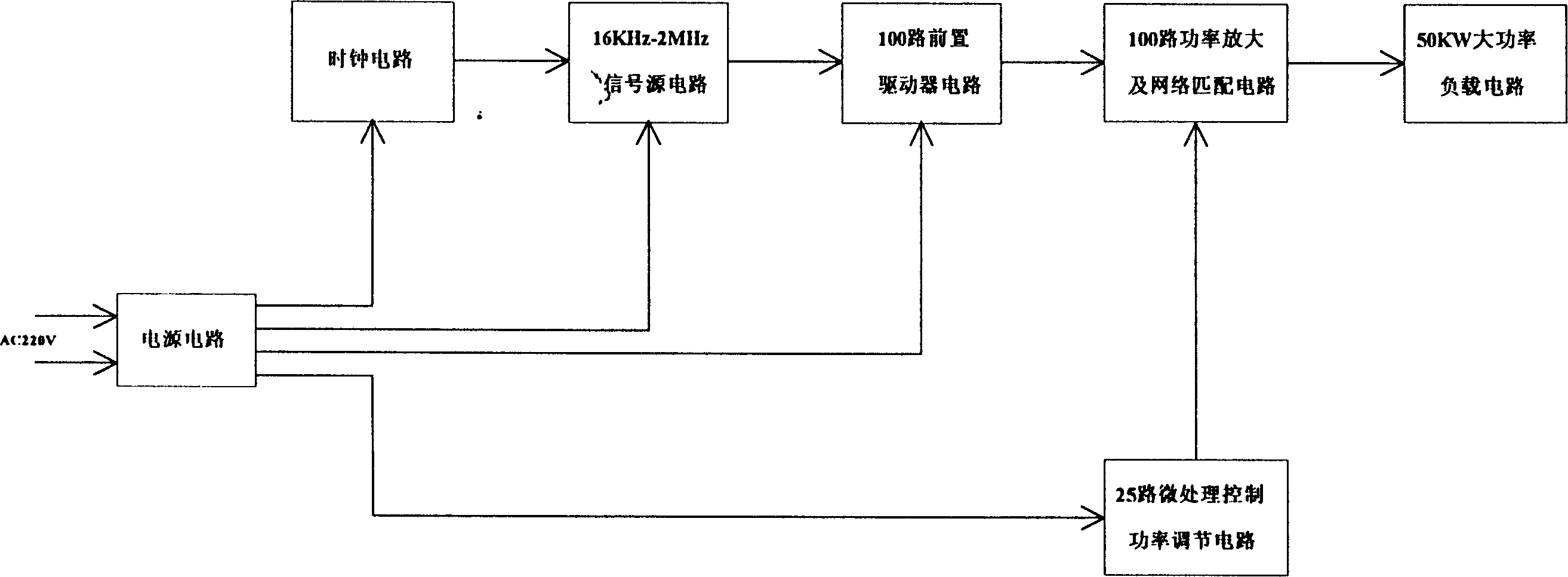
This invention relates to a super large power ultrasonic generator with one common oscillation source, which comprises the following: power circuit, time circuit, signal generator circuit, front drive circuit, microprocessor power adjusting circuit, power amplifying and matching circuit and load circuit. The signal generator makes fractional frequency division of the time signals and generates control signals with frequency range of 16KHz-2MHz according to frequency points selected. The front drive circuit converts the control signals into drive signals with one to one hundred paths. The front drive signals are amplified with power and gets output pushing signals through matching circuit to fulfill the output power adjusting and controlling.

Description

technical field [0001] The invention belongs to the power ultrasonic technology and is mainly used in the fields of ultra-high power ultrasonic cleaning, ultrasonic emulsification, ultrasonic drug extraction, ultrasonic sewage treatment and the like. Background technique [0002] The existing ultrasonic generator is the most widely used ultrasonic cleaning machine as an example, the minimum power is 50W, the maximum power is 40KW; the minimum frequency is 16KHz, and the maximum frequency is 120KHz. [0003] As far as the signal generator is concerned, existing ultrasonic generators can be divided into self-excited oscillation and other-excited oscillation to generate signal sources. [0004] As far as the output power adjustment of the existing ultrasonic generator is concerned, it is mainly completed by using a transformer to adjust the working voltage of the power amplifier and the inductance of the matching network. [0005] The technical deficiency o...

Claims


Application Information

Patent Timeline
IPC IPC(8): B06B1/02
Inventor 杜鹏胡艺
Owner 杜鹏
Why Eureka
Eureka Blog
Learn More